The Native American Banksy on Hwy 89

Share

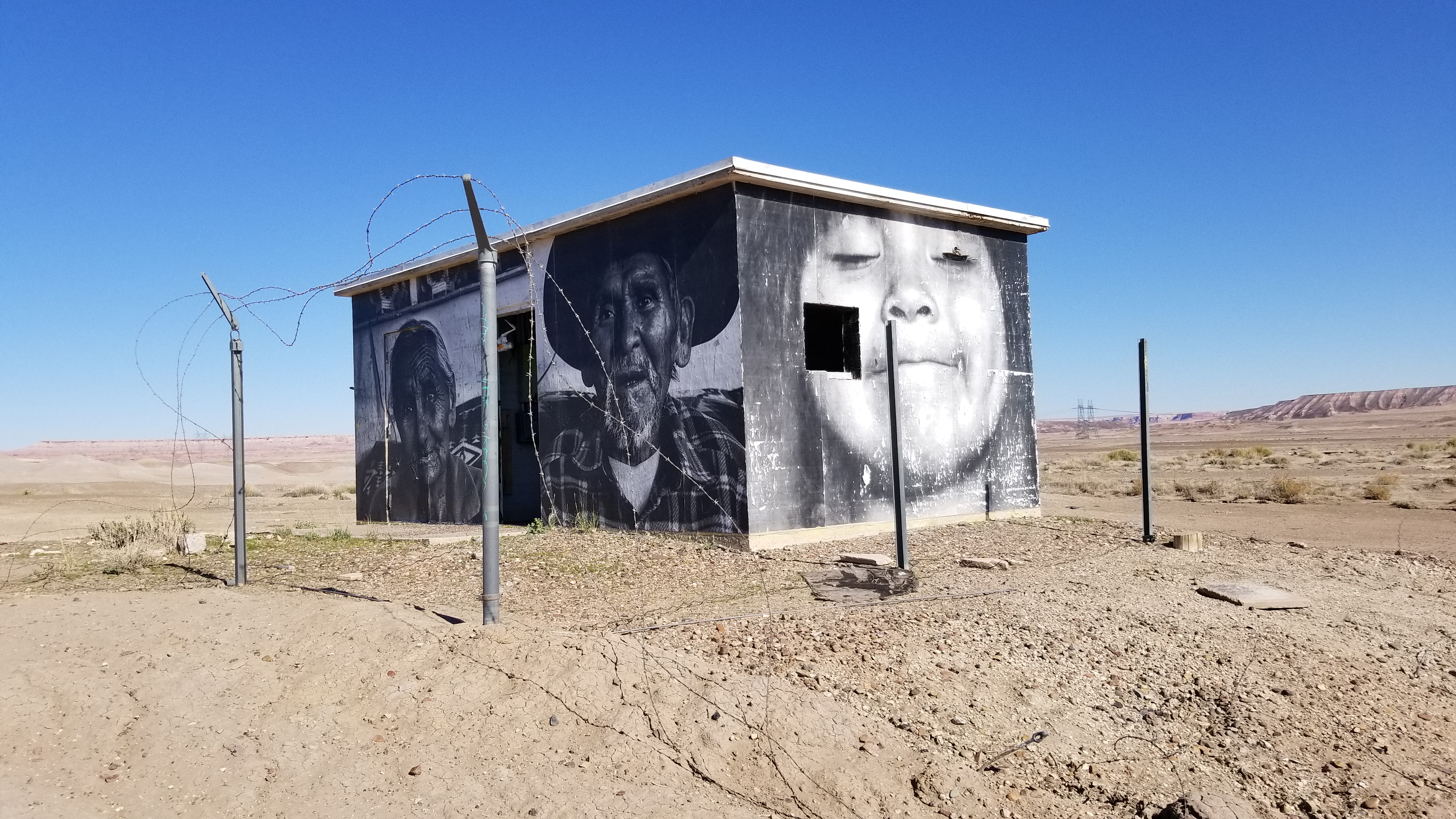
Making the drive from Phoenix, AZ to Southern Utah, it’s hard not to get lost in the gorgeous landscapes along the roadside. If you pay attention to more than the traffic and the magnificent rock, you’ll start to notice the Native American culture glimpse back at you.

The deserted truck stops, empty jewelry stands, and long abandoned broken down roadside trailers. This is a shimmer of a dead dream, or the crumbs of a forgotten life. No matter how you look at Native Americans today, it’s a sad sight to see.

A people who were driven west, lost an all out war, and nearly eradicated to extinction. The meth epidemic, the diabetes, or alcoholism are continuing to diminish the remaining numbers.

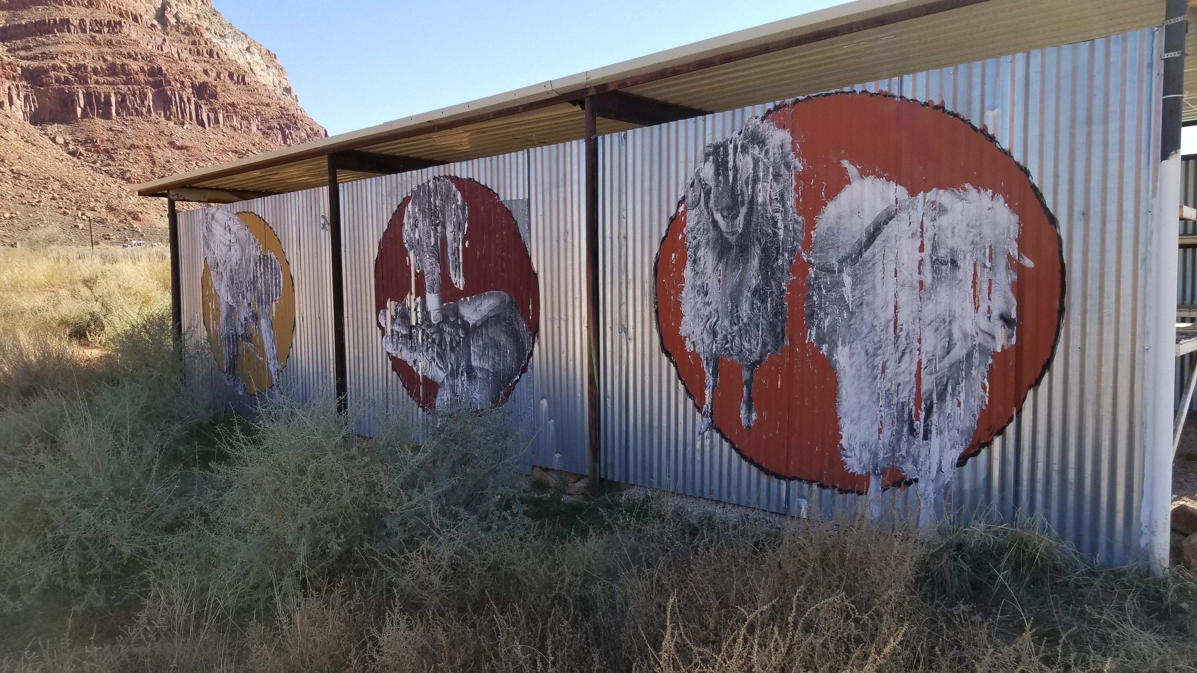
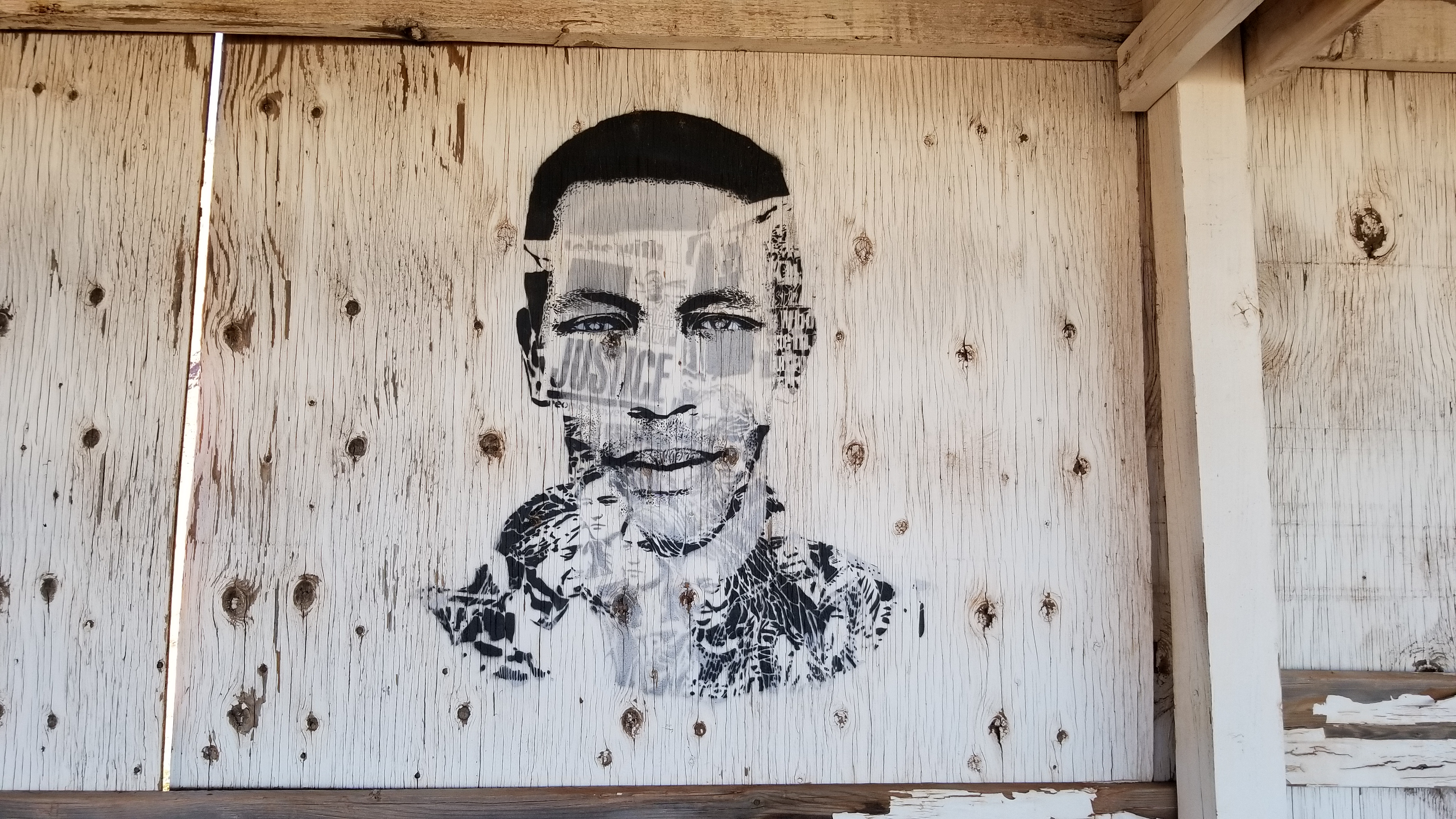
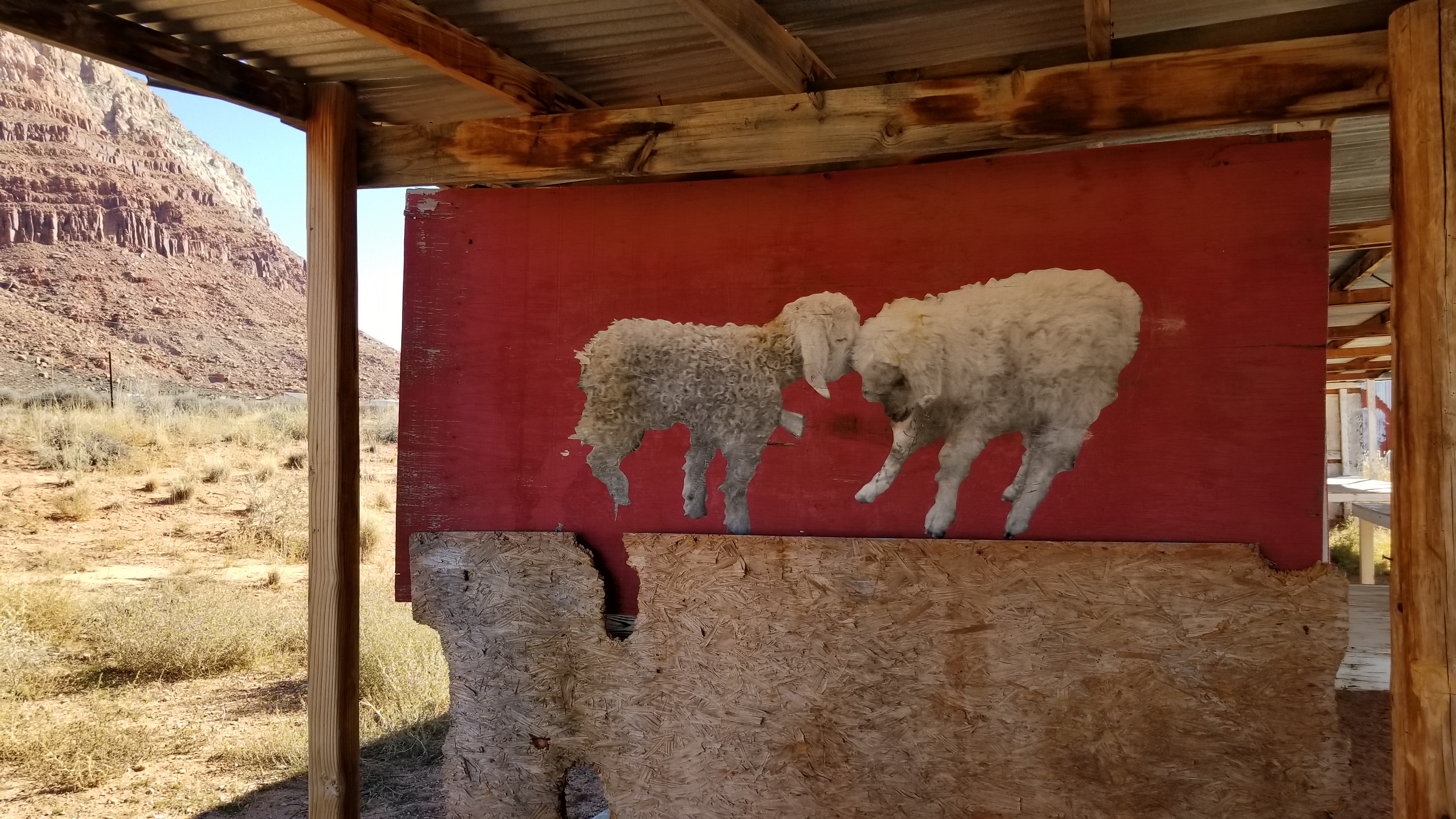
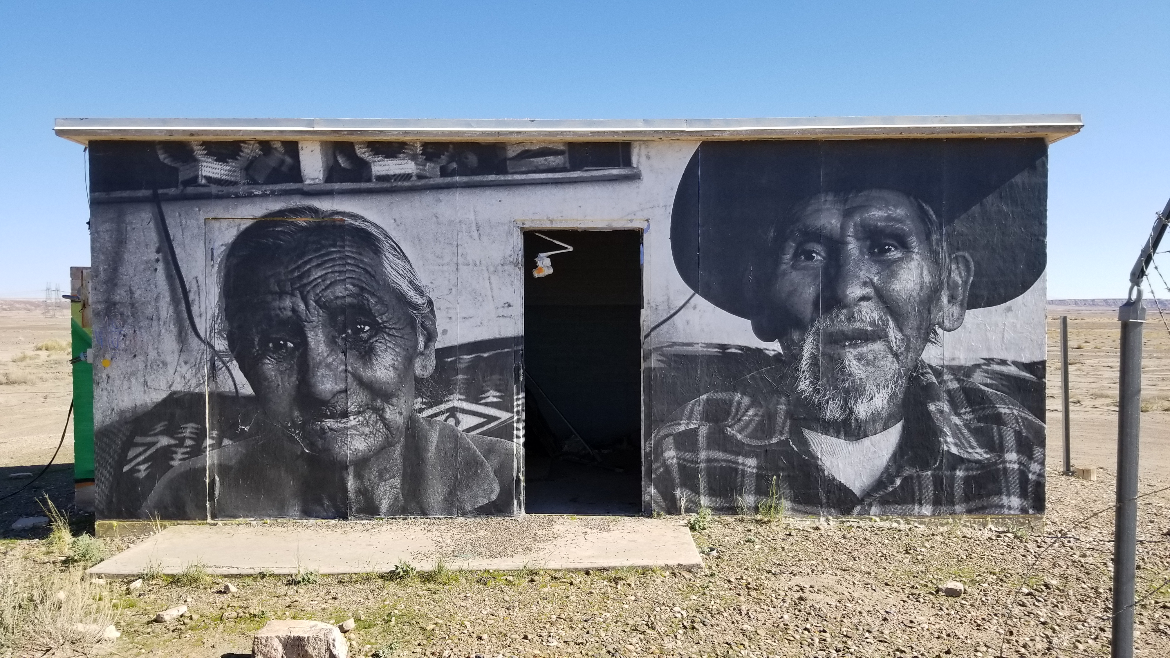
Someone out there is fed up, standing up, and making themselves heard, even if it’s from a faint cry of roadside graffiti. A stellar artist is wrapping abandoned houses and speaking from an isolated culture. Showing intimate images of family and friends in everyday settings, giving the passers by a glimpse into what Native American culture is.

They are also pulling no punches against coal companies and uranium miners coming onto native lands and taking from the soil at what I can assume is on the same level of cheapness that it took for America to obtain the Louisiana purchase from the French . . .

At any rate, the images are undeniably powerful. So the next time you’re cruising along with a soda in hand and your cigarette hanging out of your open window in this beautiful landscape, take a closer look. Some people are speaking, if you are willing to listen.

Share

CamperVan Build – Step 4: Start Laying Out Your Wire

Share

Step 4: Start laying out your wire.

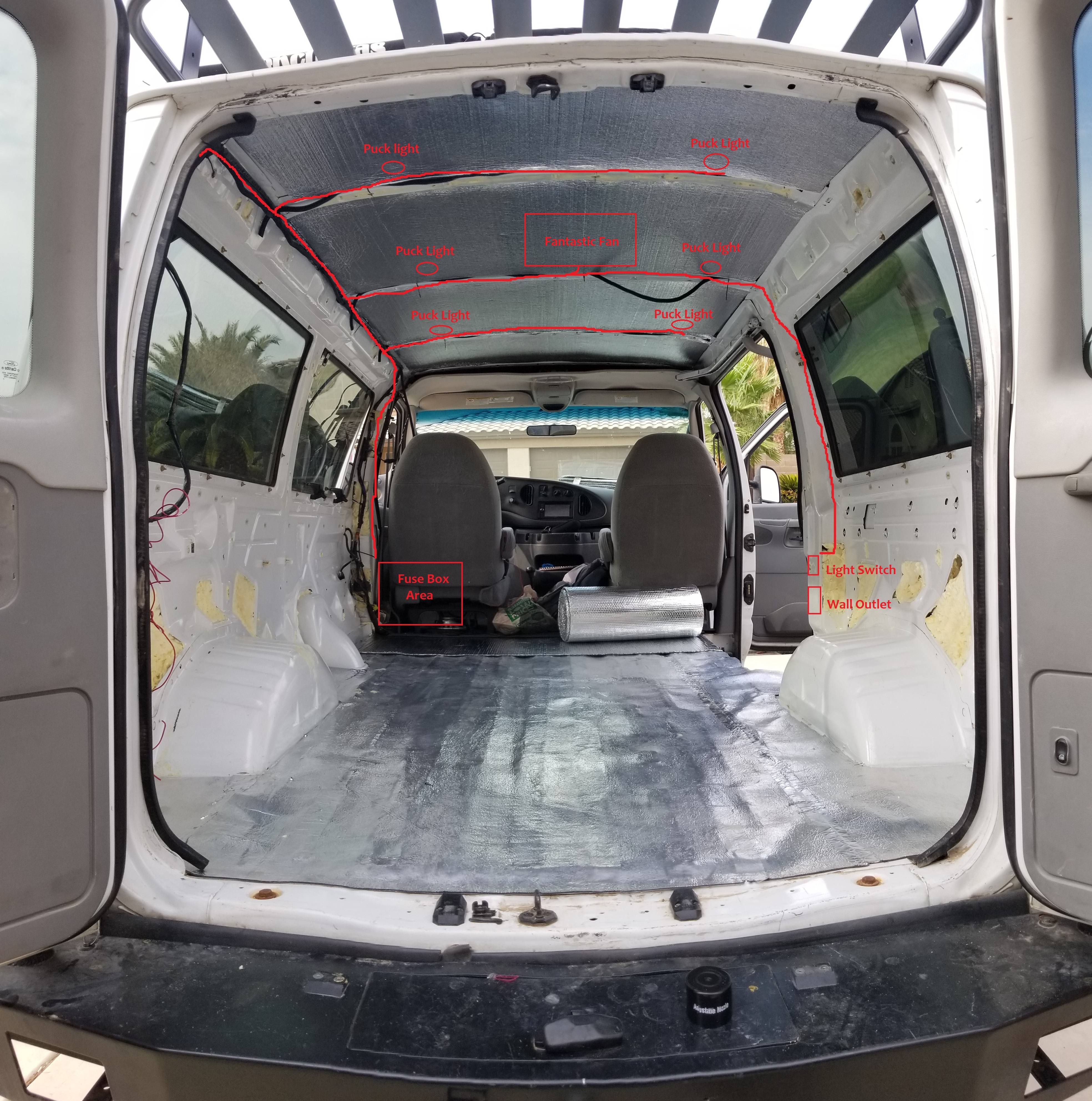
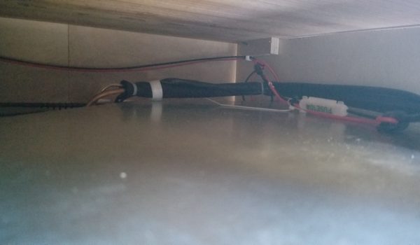
It may seem early to be wiring things up, but this critical step will ensure that you don’t insulate over or cover up area where you will need to run wires for your appliances. Decide where your central fuse box will be, you will run all your wires to this location. Your fuse box will be the central place for power distribution. I chose to locate my Fuse Box just behind the driver’s seat. Draw faux appliance locations on the sheet metal with sharpie (lights/ceiling fan) and start running your wires/sheathing. I ran most of my wires right next to the stock wiring harness along the driver’s side corner where the ceiling meets the wall. (A full description of my electrical system will be in the Electrical section).

I ran 18 AWG wire from my components to my fuse box. Check your selected appliances/components manuals which will give you a recommended wire spec. If there is no callout, use an online wire gage calculator to select the correct size of wire (https://www.wirebarn.com/Wire-Calculator-_ep_41.html)

Basic Initial Wiring Outline: More wiring will be added once the cabinet/stove/sink area is installed.

Basic Wiring Layout (Click to enlarge)
Tools / Materials used:
Phase 1/3: Wiring I ran before insulation:
  • Wall outlet + extension cord – This will be one of two wall outlets in the van that will be powered by my inverter. Location: Placed on the passenger side of the van, just on the column to the left of the sliding door. I ran the wires up and across the ceiling next to a C brace and along the driver’s side upper ceiling/wall brace down the column to my intended fuse box location.
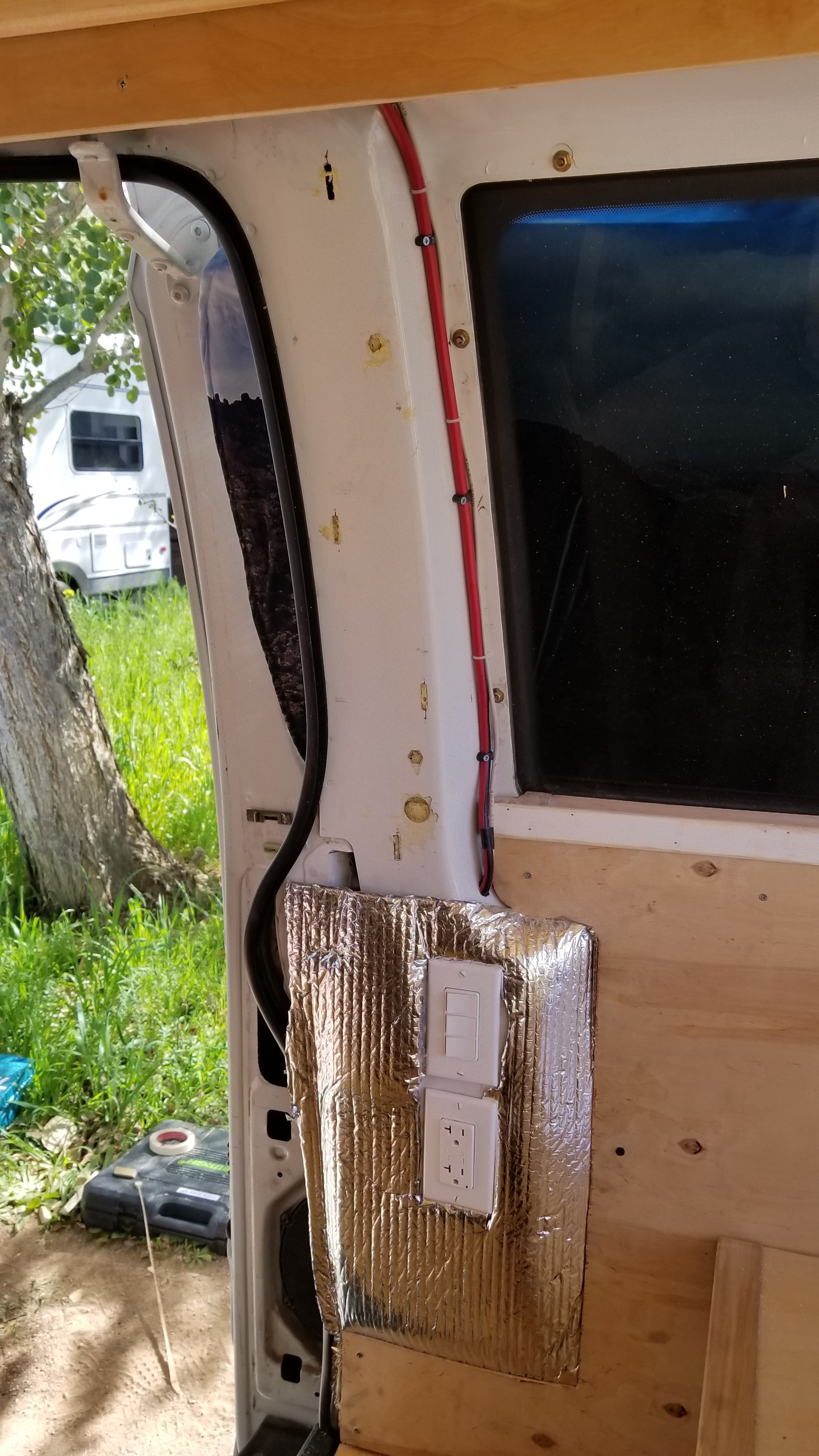
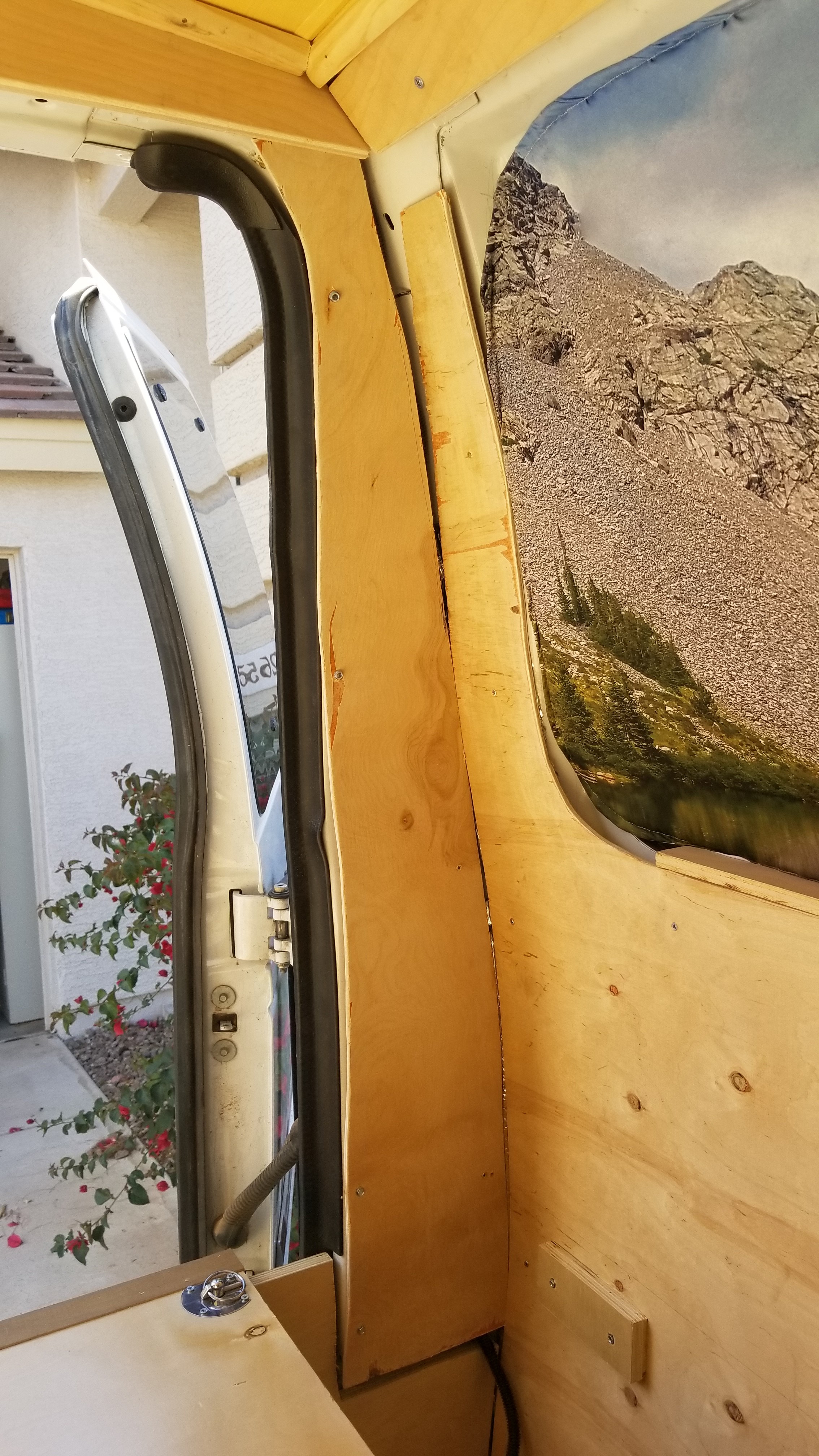
    • Side Note: I cut out the metal from the sliding door column to fit the 2 blue outlet boxes for the 3 way switch and 120V outlet. I drilled 4 holes, 1 at each corner for the box then used a Dremel or Grinder to cut the hole and fit the box in place. I used a chisel and hammer to get some of the metal out of the way. I drilled through the rear passenger window frame (lower left side) from above to run the wires coming down from the ceiling to the boxes now installed in the sliding door column.
    • Showing 3 Way Switch and Outlet installed on the sliding door column
  • 3 Way Light Wall switches – I will later wire these in to operate my main ceiling LEDs, indirect lighting LEDs, and over the kitchen area LEDs. Location: I put these switches right next to the wall outlet and ran the wires right next to the wall outlets wires.
  • Ceiling LEDs – I used 6 puck LEDs on my ceiling and ran wires to their intended locations. I ran the wires next to the stock wiring harness on the ceiling/wall brace then out along each ceiling brace to the puck’s intended location.
  • Fantastic Fan – I ran these wires to the general area where I planned on installing my fan (went right next to the puck light wires in the same area).
  • Video showing wiring progress: https://youtu.be/XGGkfFPyyGo (don’t be alarmed how far along I am, I just took this video a lot later than I originally planned . . . and with only a headlamp . . . sorry)
Phase 2/3 & Phase 3/3 will be completed later in the build. I added them below for understanding what wiring you will be looking forward to in the future. 
Phase 2/3: Wiring I ran during ceiling installation (Covered in more detail in the Electrical Step 10)
  • Puck Lights – As I installed my ceiling I installed my puck lights and wired them in. The end of the wires just hung in the fuse box area until I built the cabinet and installed the actual fuse box.
  • Fantastic Fan – I opted to install the fan after I installed my ceiling (some want to do this before). Once installed I soldered it into the wires I ran before the insulation.
Showing wires ran for the puck lights in the ceiling
Phase 3/3: Wiring I ran after cabinet build (Covered in more detail in the Electrical Step 10):
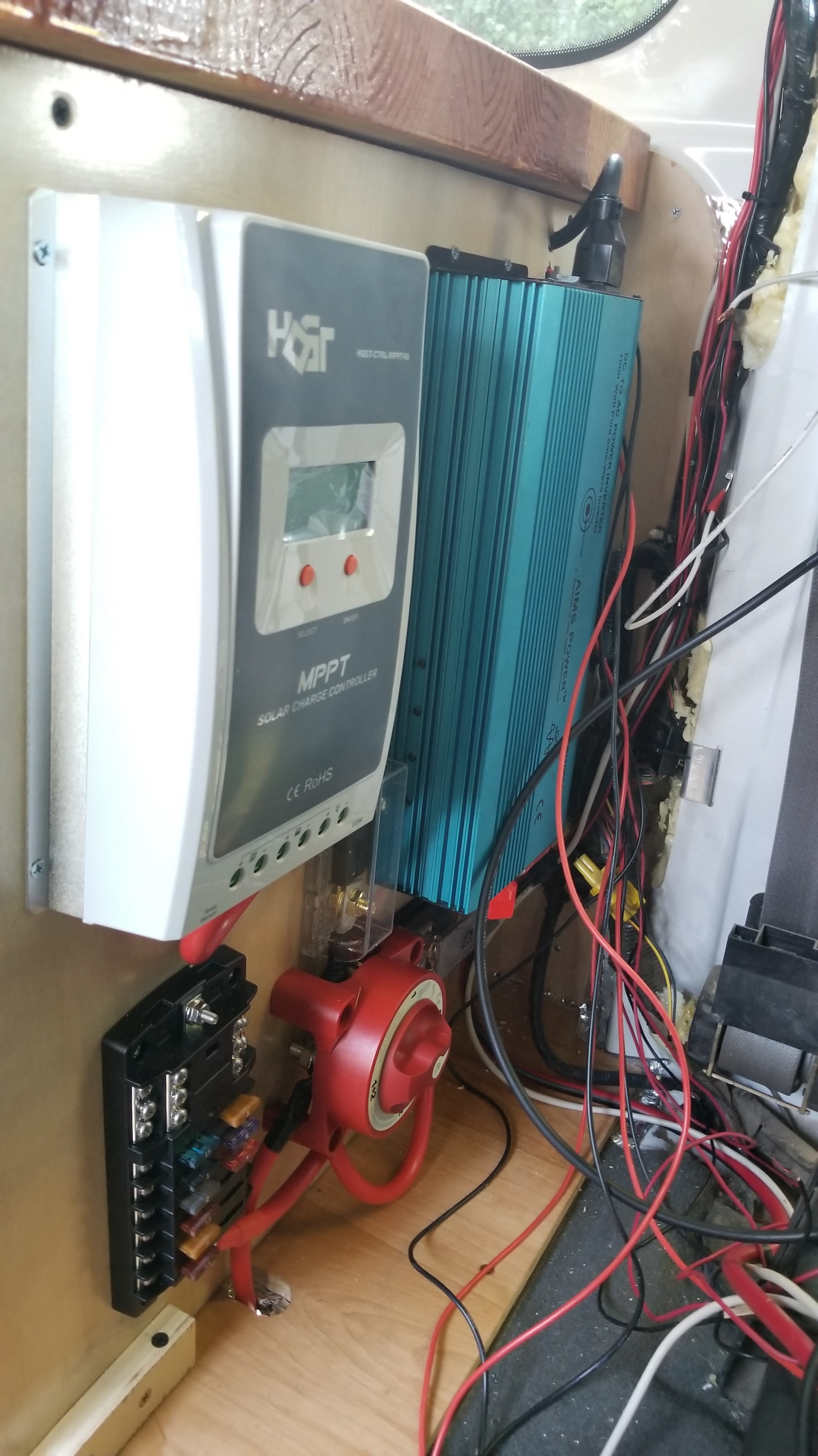
  • Charge Controller, Inverter, Fuse Block, Cutoff Switch, Fuses (all per manual specs). Installation will be covered in more detail in the Electrical Step.
  • Wall outlet + extension cord – This will be one of two wall outlets in the van that will be powered by my inverter. Location: Placed on the face of the cabinet. The wiring is ran on the upper back face of the cabinet.
  • Wiring for water pump – I mounted the water pump just below the sink and ran the wires along the back upper face of the cabinet to the fuse box. I also included a cutoff switch on the face of the cabinet to turn it off when not in use.
  • Refrigerator wiring – I ran the wires through the upper back face of the cabinet through the end to the fusebox once I installed the refrigerator (all per fridge manual specs).
  • Video Showing almost complete wiring progress: https://www.youtube.com/watch?v=YqlrzXS5fnU
Fuse Box Area almost complete
Share

CamperVan Build – Step 5: Insulate

Share

Step 5: Insulate

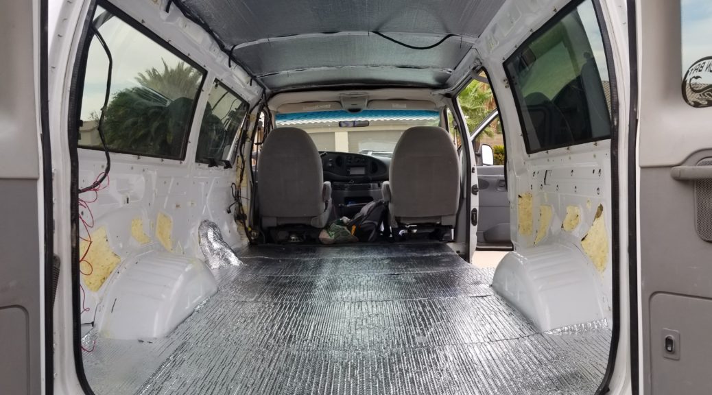
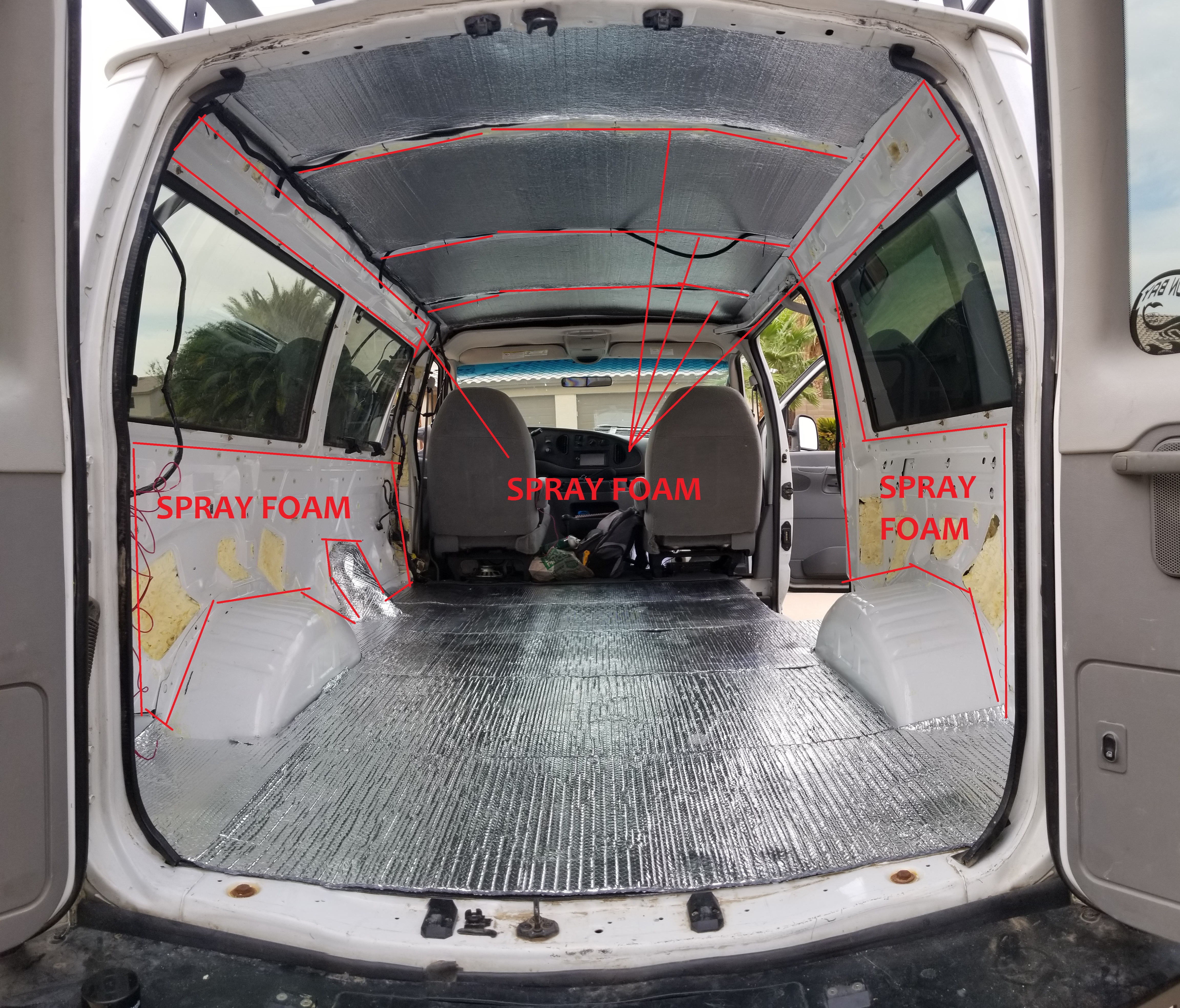
Now that you have a clean base, let’s start insulating this guy! My E-350 was a passenger van and not a cargo van, so that means the interior sheet metal walls are designed and contoured to receive the plastic molding (that you removed in Step 3). This means there are large gaps between the outer sheet-metal of the van body, and the inner wall sheet-metal. Due to this I decided to use spray foam for these gaps as it is hard to use anything else in these gaps (no accessibility).

Tools / Materials used:
Procedure:
  • Start by spray foaming inside the walls and braces. Caution! Apply the spray foam in stages. The foam needs to cure and if you spray a ton in at once it will not cure in the middle. The foam is very sticky and will ruin your clothes. If you get it on yourself (or your hair), wash it off immediately! Note: The two cavities in the rear corners of your van where the wiring harness for your brake lights should be partially left clear so you can still maintain the wiring/lights.

  • Ceiling insulation – Install the hard foam into the roof (I used 3M spray-on adhesive to hold it in place). I cut the hard foam to fit between the braces, making enough room for the wiring sheath that you installed in the Lay the Wiring Step. I used 3M adhesive spray to hold it in place.
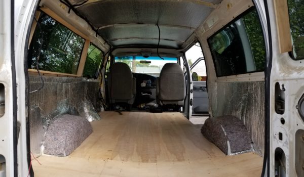
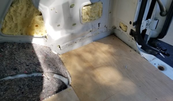
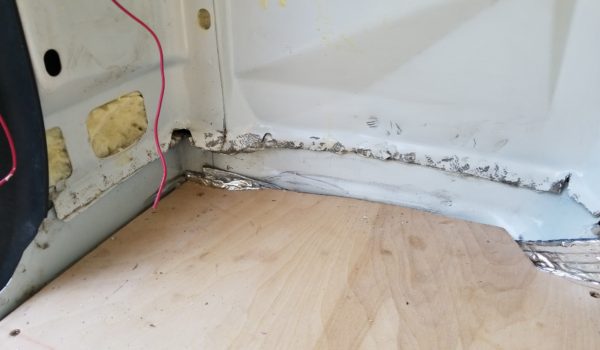
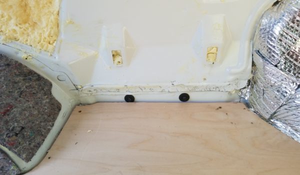
  • Subfloor barrier installation (You can use this as a floor template to cut your wood before you glue it down!)- You want to remove any bolts that are left over from securing seats, seatbelts, or any other components you removed when you stripped the van out. Make sure the floor is clear of anything before installing the subfloor barrier. Once my flooring was ready (and I wasn’t tramping in and out of the van left and right) I cut the subflooring barrier for the floor, and installed it using 3M adhesive spray.

  • Subfloor reflexive insulation – Cut the reflexive for the floor, installed on top of the subflooring barrier, hold in place using 3M adhesive spray.

  • Install the reflexive on the walls (custom cut) using 3M adhesive spray. I would later cover these areas with wood.
    • NOTE: My particular passenger van had a metal tab/lip that protruded out which would obstruct the wood walls from going down to the floor. I took a large hammer and beat this tab/lip flat so I had a good surface to work with. Then I placed reflexive over this. Video: https://youtu.be/NPkwn7DhH-M
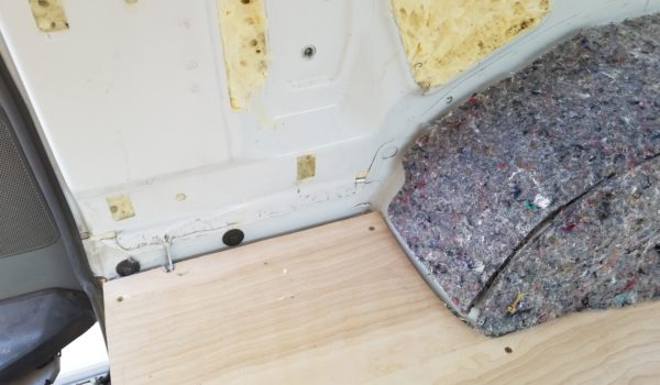
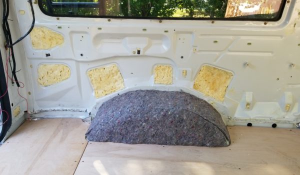
  • Take the insulation attached to the bottom of the carpet you removed in the Strip Step made for the wheel wells and reinstall it over the wheel wells. I tore this off the bottom of the carpet, sprayed 3M adhesive and stuck them back on.
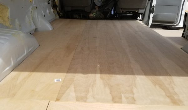
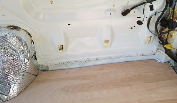
Reflectix in, Jumped ahead and put the floor in too (covered in the next step!)

Videos:

Share

CamperVan Build – Step 6: Wood Floors, Ceiling, and Walls

Share

Step 6: Wood Floors, Ceiling, and Walls.

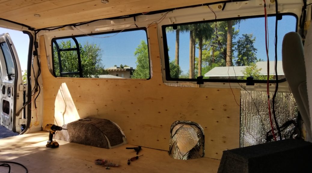
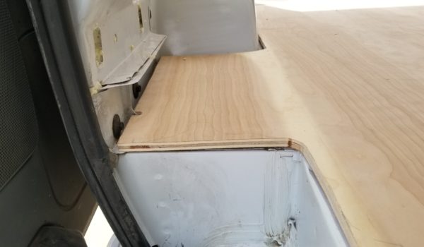
It’s time to give your dream some form. Pretty much you want to cover all the areas you insulated so you can start building your storage areas. I chose to go with a plywood floor, thin plywood walls (thin enough to bend/contour to the shape of my van), tongue-and-groove ceiling. Tons of different flooring/ceiling options out there just make sure the floor can take a beating, because it will! Nothing in your van is flat. Front-to-back, side-to-side, almost no surface in the E-350 has perfect right angles, so you will be constantly cutting custom shapes (put into place, make a mark, remove, cut, repeat until it fits).

Tools /Materials used:

Procedure:

Flooring:

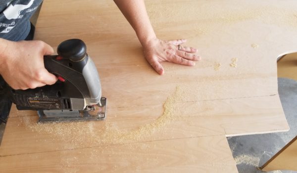
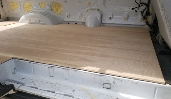
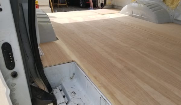
  1. Use the carpet as a template for your plywood flooring. I ended up using 2 sheets and cutting them into 3 pieces to fit the floor of the van.
  2. Use a chalk-line tool to indicate the location of the ribs of the floor of the van. I wanted to make sure I was getting a good interface between the wood and the van’s sheet metal floor below the insulation.
  3. I drilled small pilot holes, and then used screws to secure it to the floor.
    • Caution! Ensure that your screws aren’t too long! You could potentially put a screw through the floor and hit wiring or another component beneath your frame, so keep that in mind!
  4. You’ll seal and paint this after the bed and the cabinets are installed. You can do this before if you like, your call.
  • Use the subfloor insulation as a template and start cutting!
Floor Install Video:

https://youtu.be/zaIeNZoCrNg

 Ceiling:

  1. First stain and seal the wood if you are planning to, before you put them in (save yourself some overhead work like I had to go through, lesson learned:
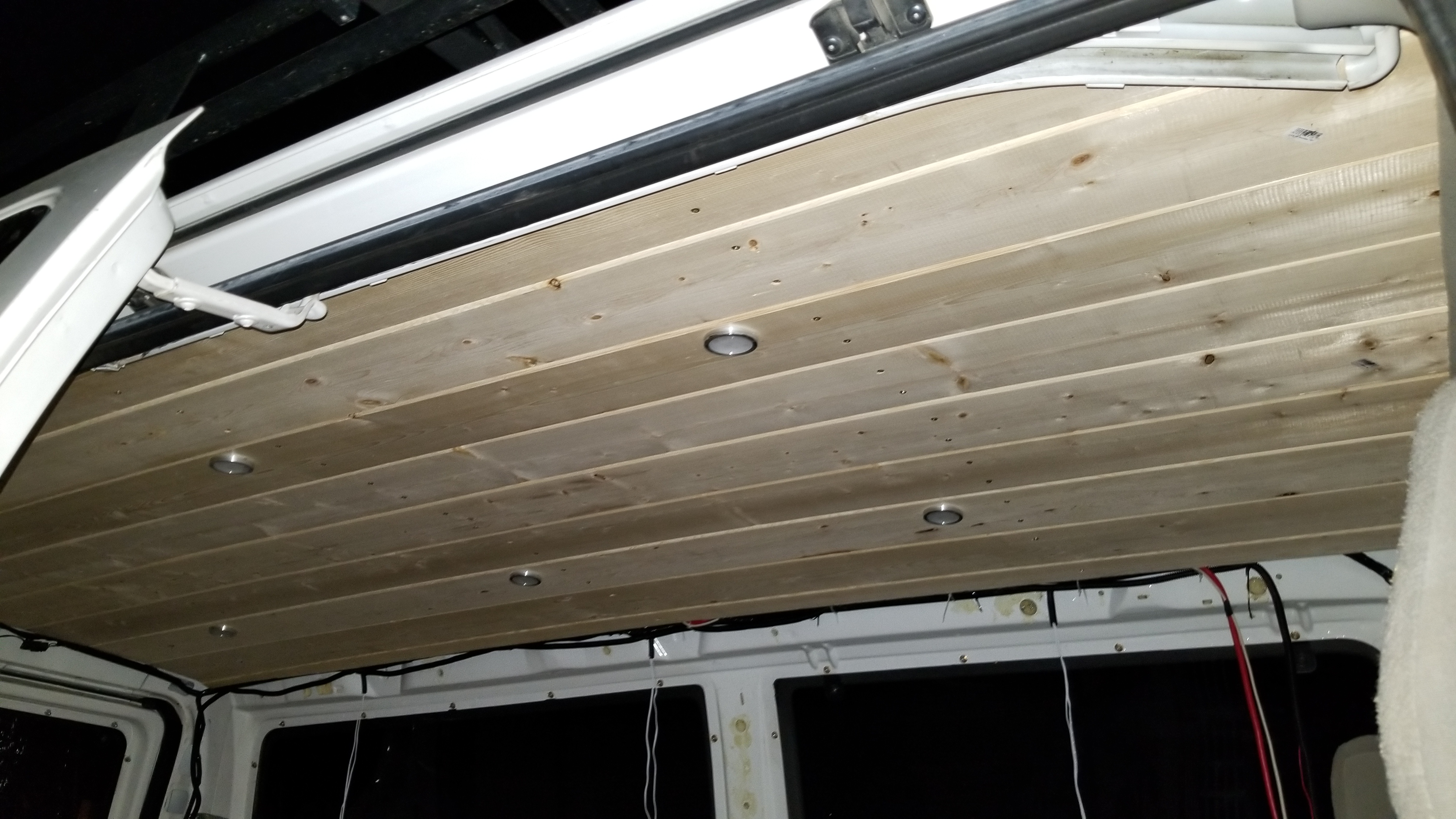
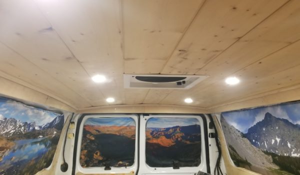
  2. I butted up my first tongue-and-groove piece against the passenger side of the van (Note: from what I’ve seen, if you want perfect symmetry you should start in the center of the van and work outwards, lesson learned). I cut the tongue off this first piece so it would snug up nicely to the edge. I screwed the first piece in where the ribs of the vans ceiling were to secure it in place (make sure your screws aren’t too long as you don’t want a hole in your roof!). I moved along towards the driver’s side, fitting in the next piece and snugging it up before screwing it in. Once I reached a board where I planned to have a puck light installed, I drilled a hole through the board for the puck light wires, ran the wires through, installed the puck light to the board, and snugged it up before screwing it in place. I continued this process until I reached the driver’s side of the van’s ceiling. For the last piece I had to cut a custom sized board to fit in place (this was a pain in the butt to get the last piece in, but it was tight and eventually went). Nothing in this van is flat and everything you cut will be custom.
In progress, working from passenger to drivers side
All installed, another late night!
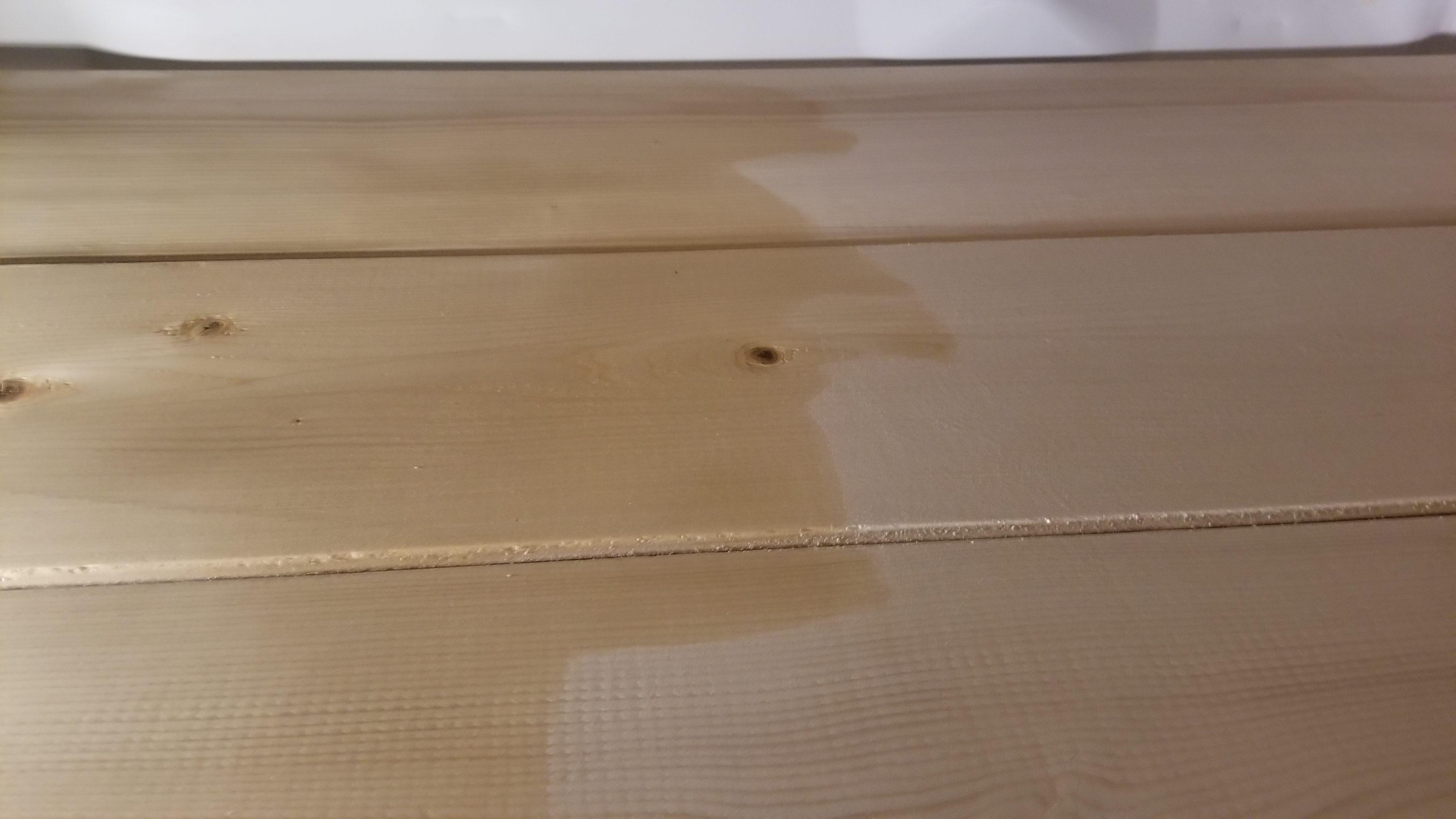
Like a silly person, I stained my wood after it was installed . . . save yourself the trouble and do this BEFORE installing!
Stain!
Stain it, it will make a huge difference!
Ceiling Install Videos:

 Walls:

  1. My particular passenger van had a metal tab/lip that protruded out which would obstruct the wood walls from going down to the floor. I took a large hammer and beat this tab/lip flat so I had a good surface to work with (I covered this in the insulation section, but wanted to note it just in case you insulated your van differently).
    Video: https://youtu.be/NPkwn7DhH-M
    • Lip beat down!
  2. I used a thin (0.20” thick) piece of plywood for my walls. I chose something thin so it would bend with the shape of the van’s sheet metal. This step was quite a pain to be honest. I wanted to keep the wood in one piece if possible, which means a lot of custom work, templates, fitting, marking, cutting, in and out of the van like 30 times before you finally have the right piece to fit. Once you have the right fit, screw it into place with appropriate sized screws (drill pilot holes) for where you are placing it.
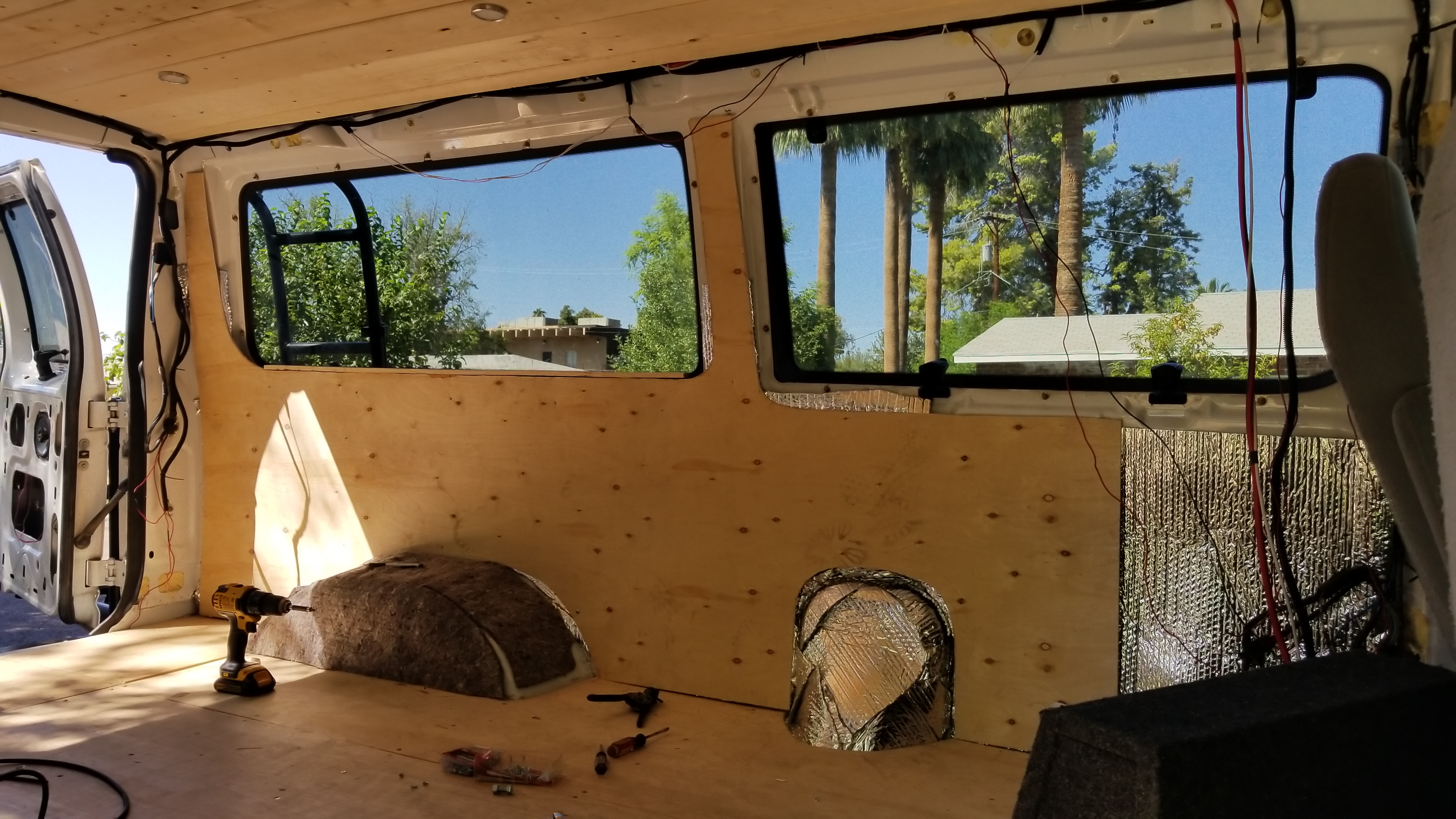
    Walls up and in!
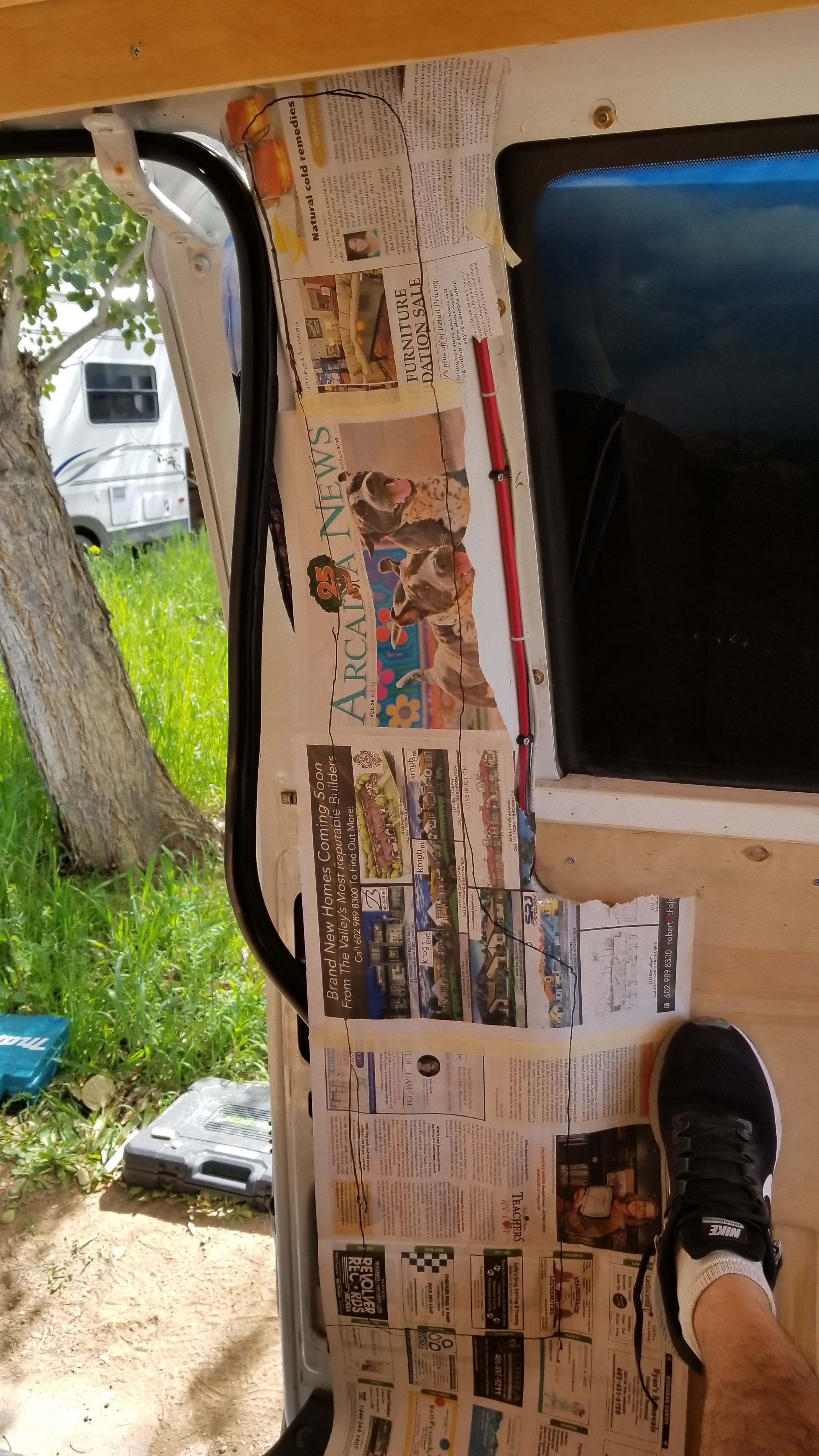
    Custom back wall pieces cut with a newspaper template. I put this off until later in the build because I was dreading it, just go ahead and get it over with before the upper facer boards go in!
    Walls in progress!
    Use newspaper where you can for custom templates, it’ll save your sanity a little!
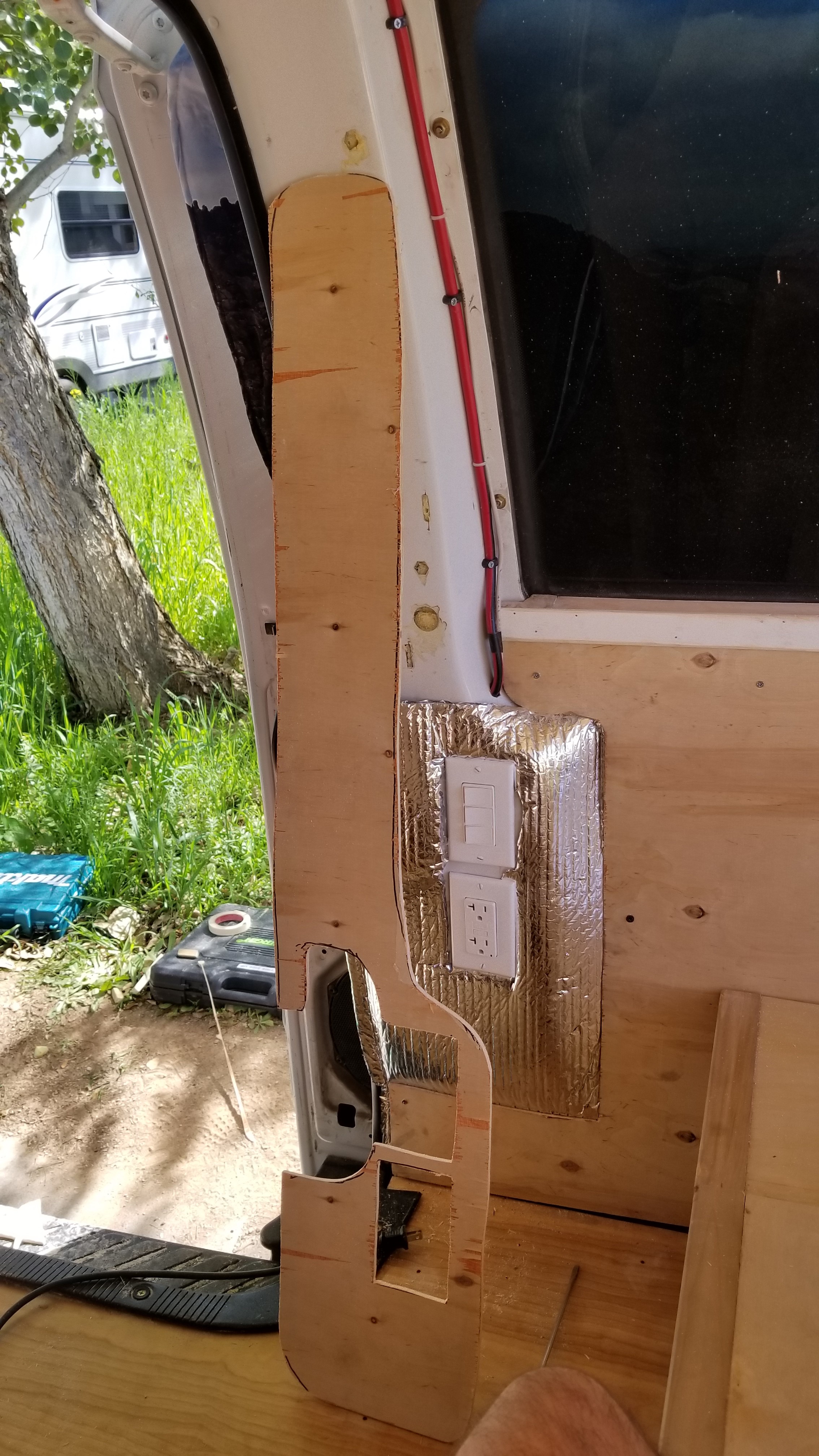
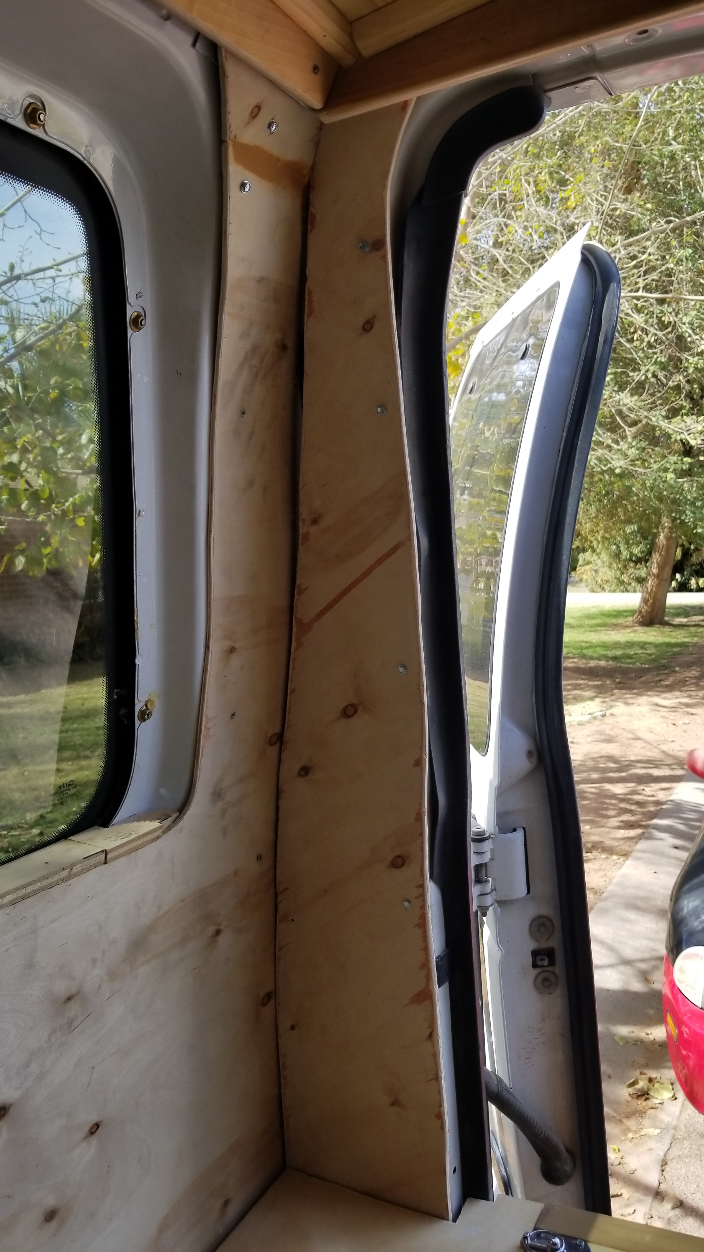
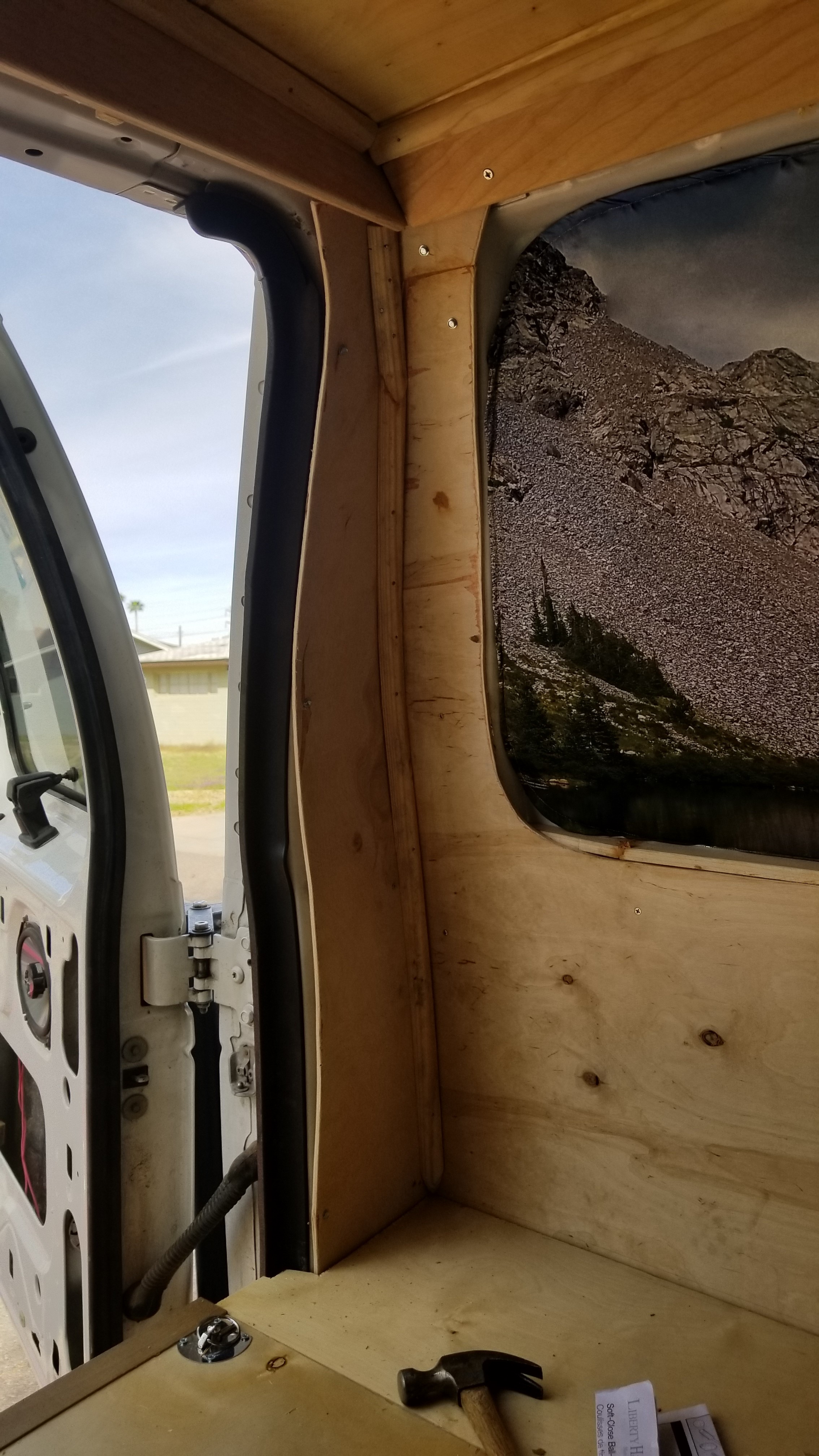
    Presto! Custom panel for sliding door column!
    1. Video for back wall: https://youtu.be/1_sF3UDD9Ho
    2. Video for wall outlet custom panel: https://youtu.be/a8fKACTMUuI
  3. Leave the back corners where the back face of the van and the sidewalls meet open (I finished these up with quarter round later after I finished installing the bed and before paint)

Upper Facer Boards:

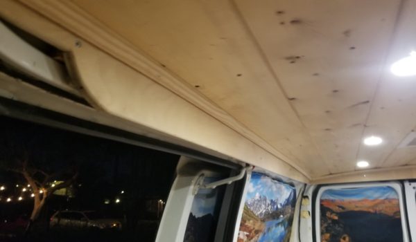
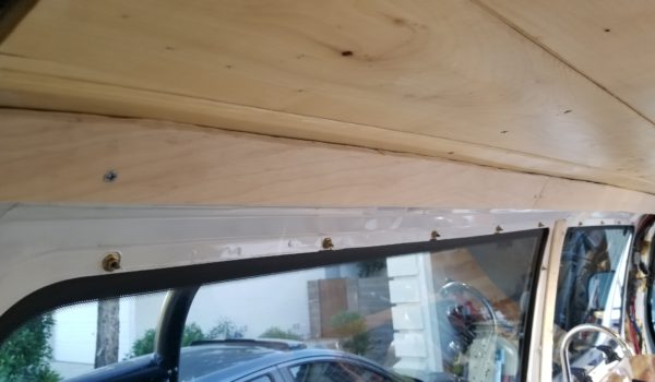
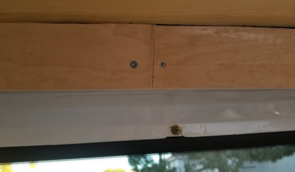
Create upper facer boards for the edges of the ceiling/walls. I wanted to create a lip that I could tuck an LED strip behind for indirect light as well as hiding all the wiring and blemishes or the bare metal van body.

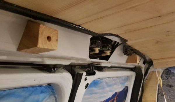
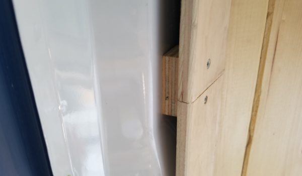
  1. Cutting custom mounting standoff blocks to ensure I had space behind the facer boards for the LED strip lights. Screw these to the metal frame of the van along the brace where the wall and ceiling meet.
  2. Cut custom facer boards for the length of all 3 walls.
  3. Install the facer boards onto the mounting blocks you have in place.
  4. Once complete I buttoned it together with a strip of quarter round at the interface between the wooden ceiling and this upper facer board, then glued and nailed into place.
  • Create custom standoff blocks for your facure boards all around the side and back walls!
  1. Now that the upper facer board and ceiling is complete, you can put the cab roof liner back into place. I used some short wood screws to accomplish this.
Share

CamperVan Build – Step 7: Build Bed/Bed Storage

Share

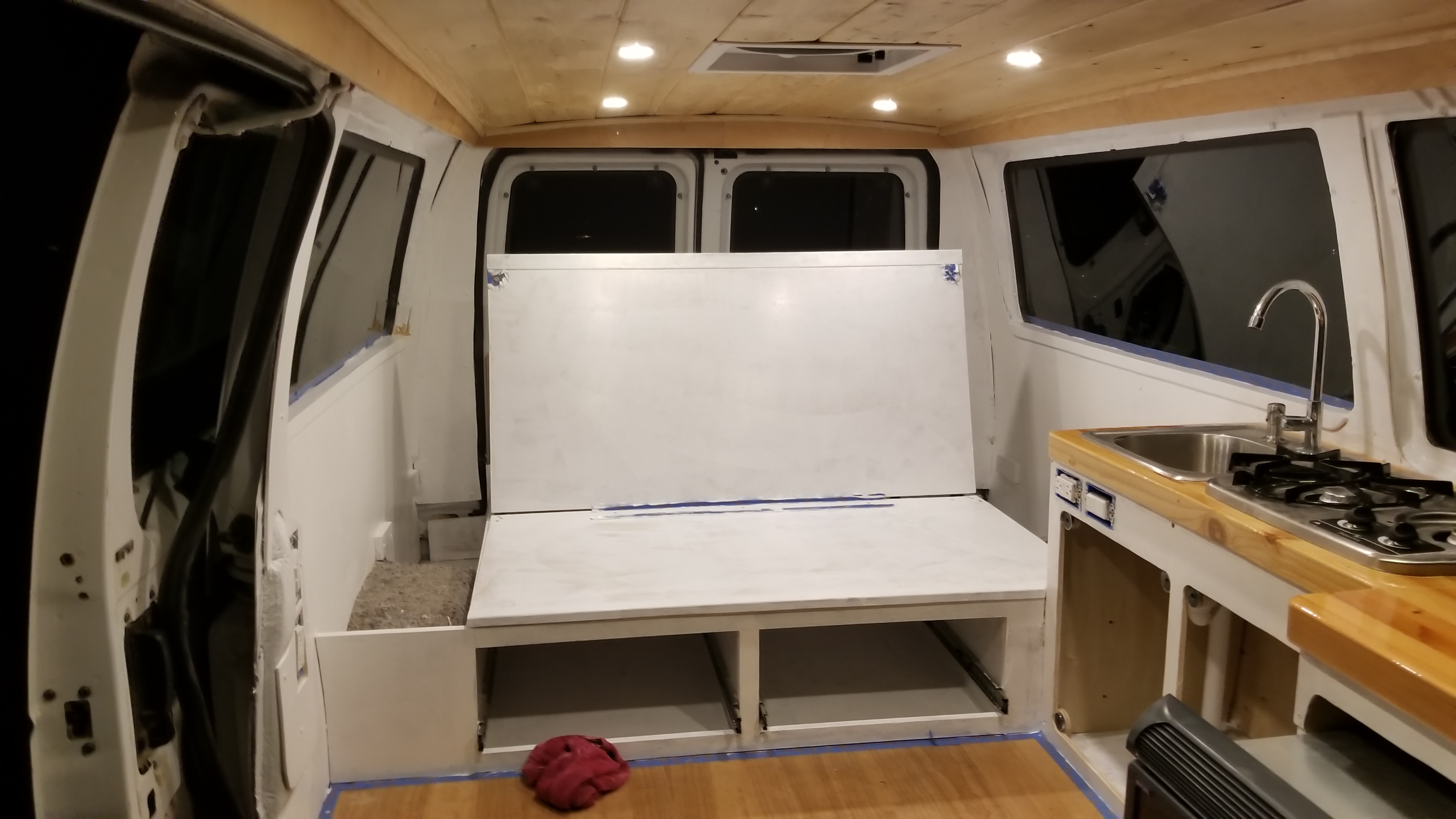
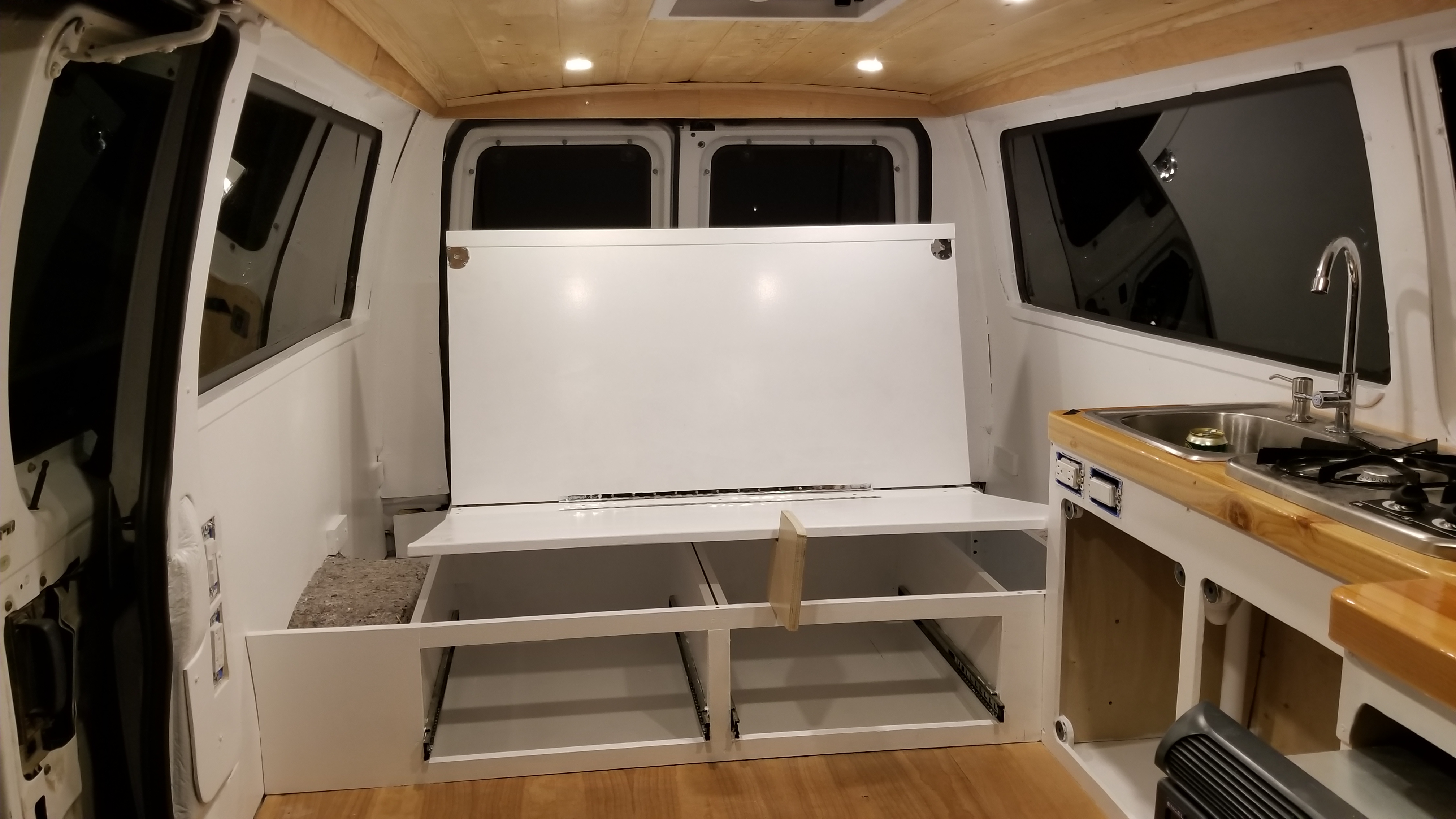
Step 7: Build Bed/Bed Storage.

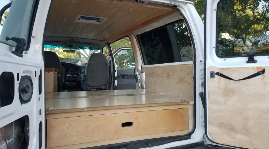
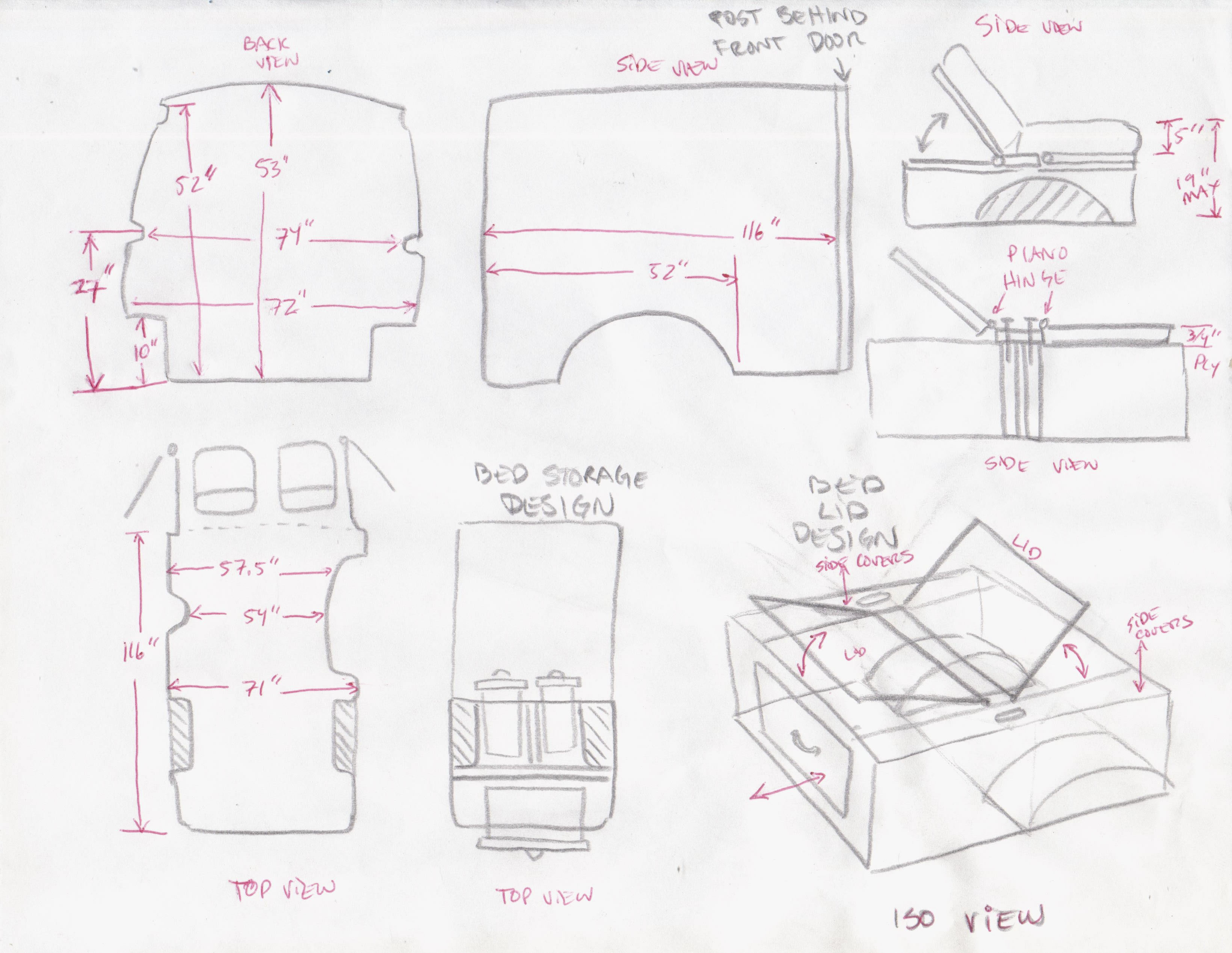
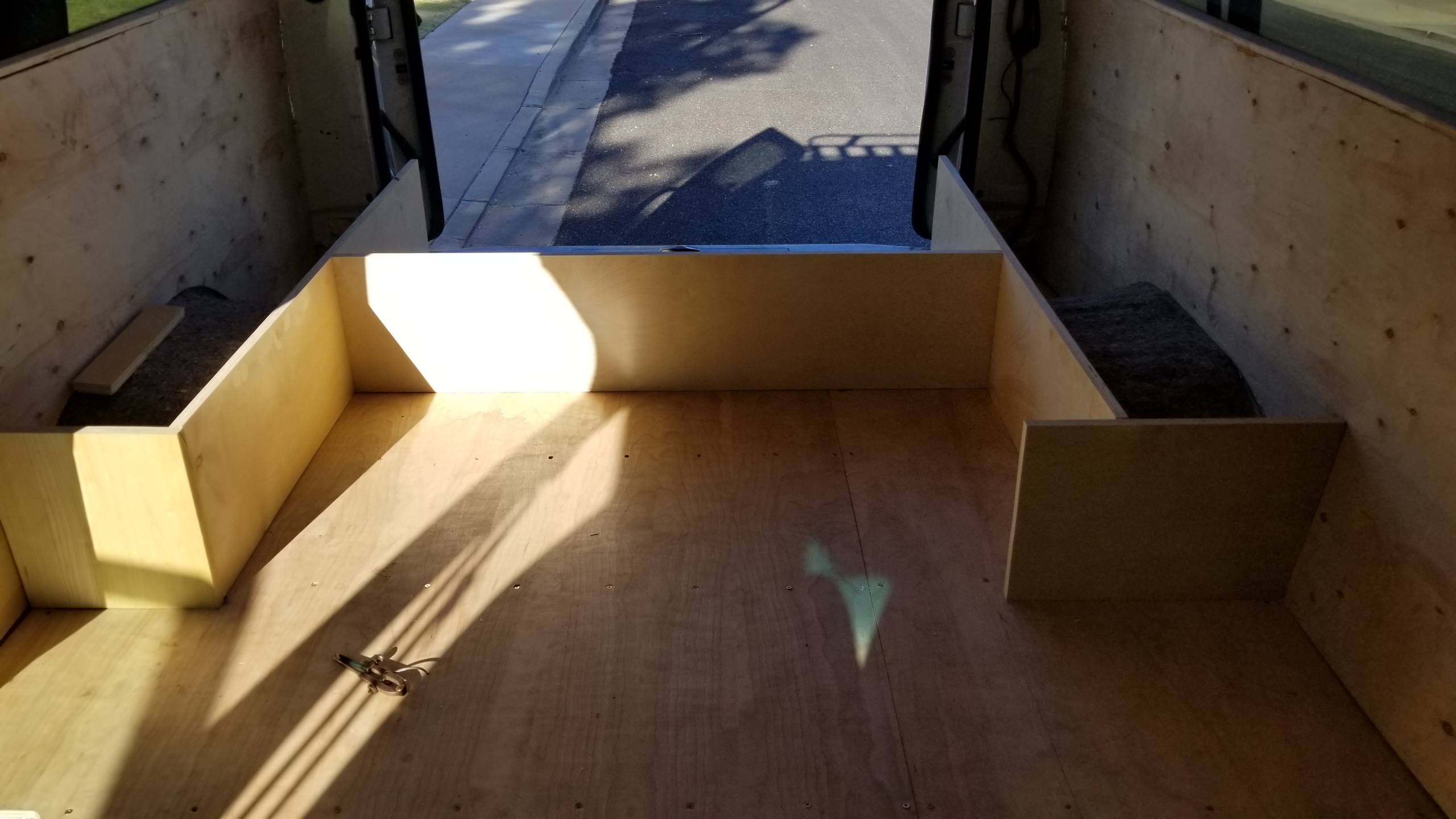
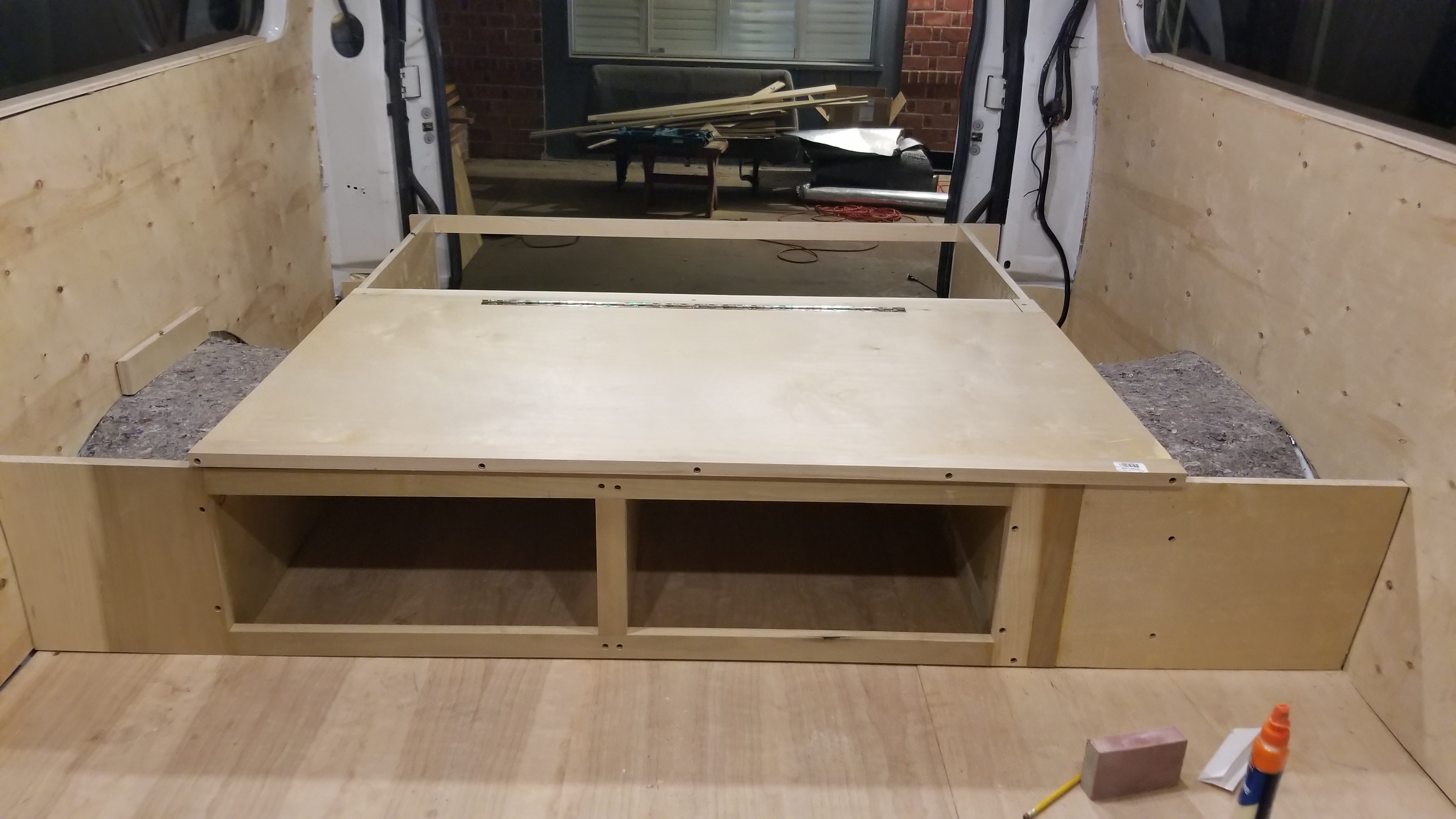
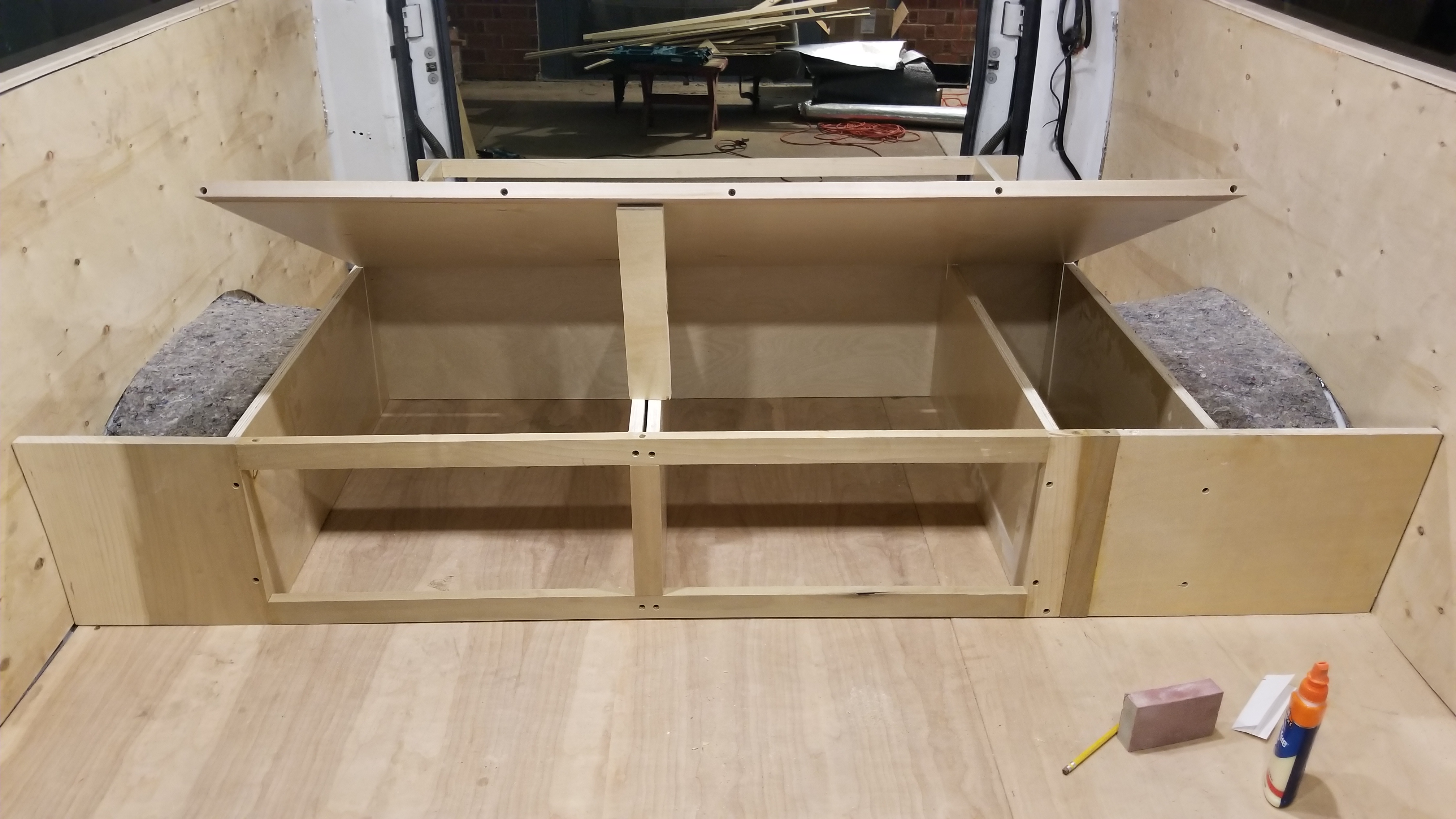
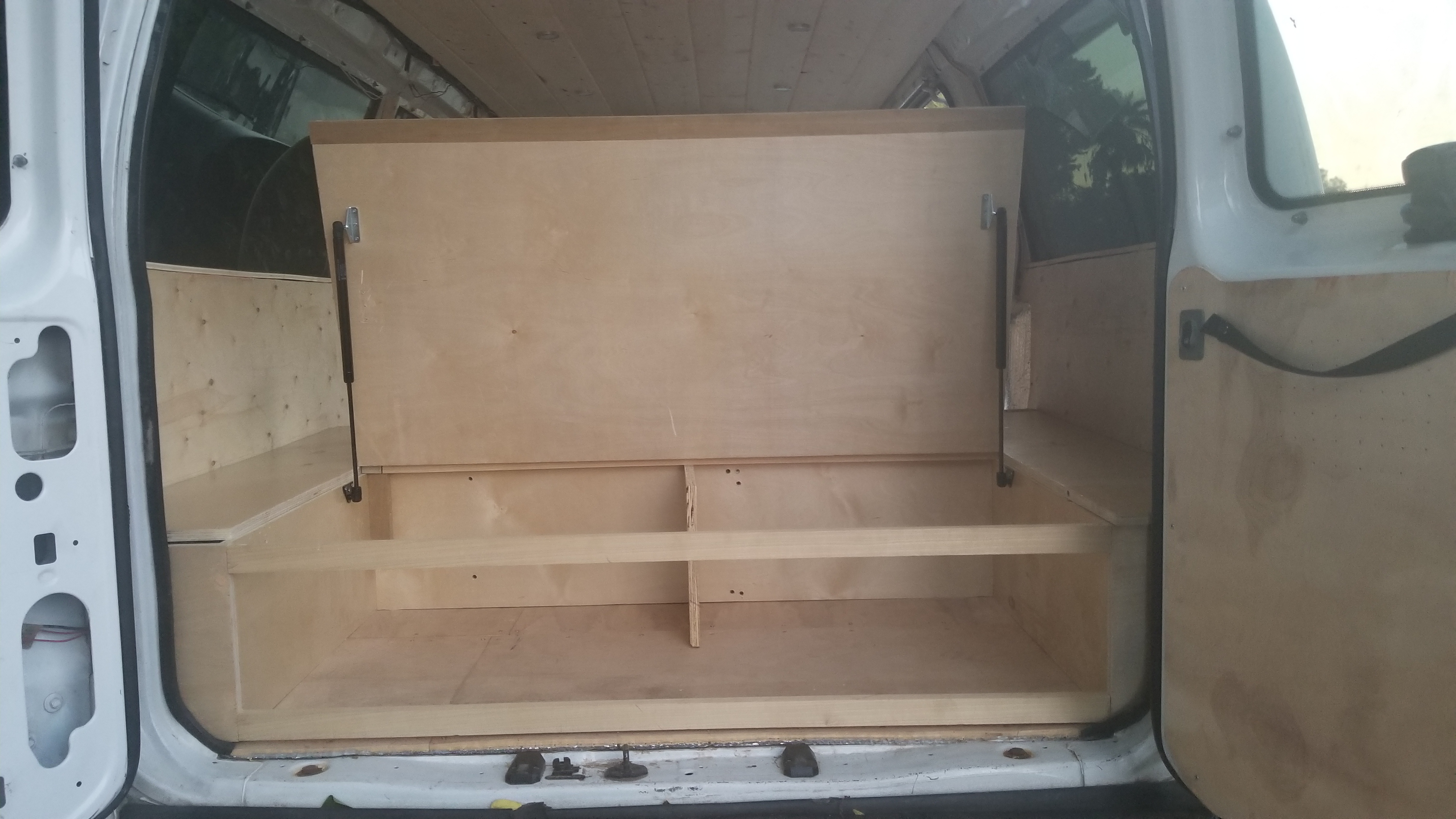
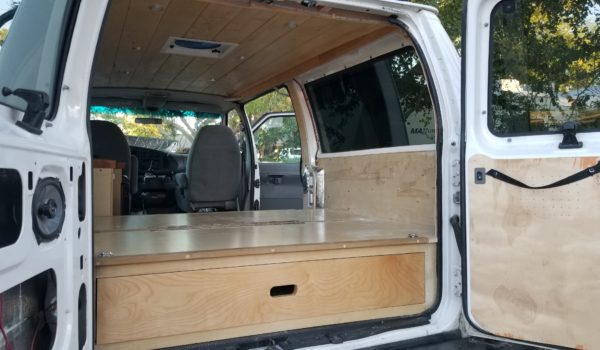
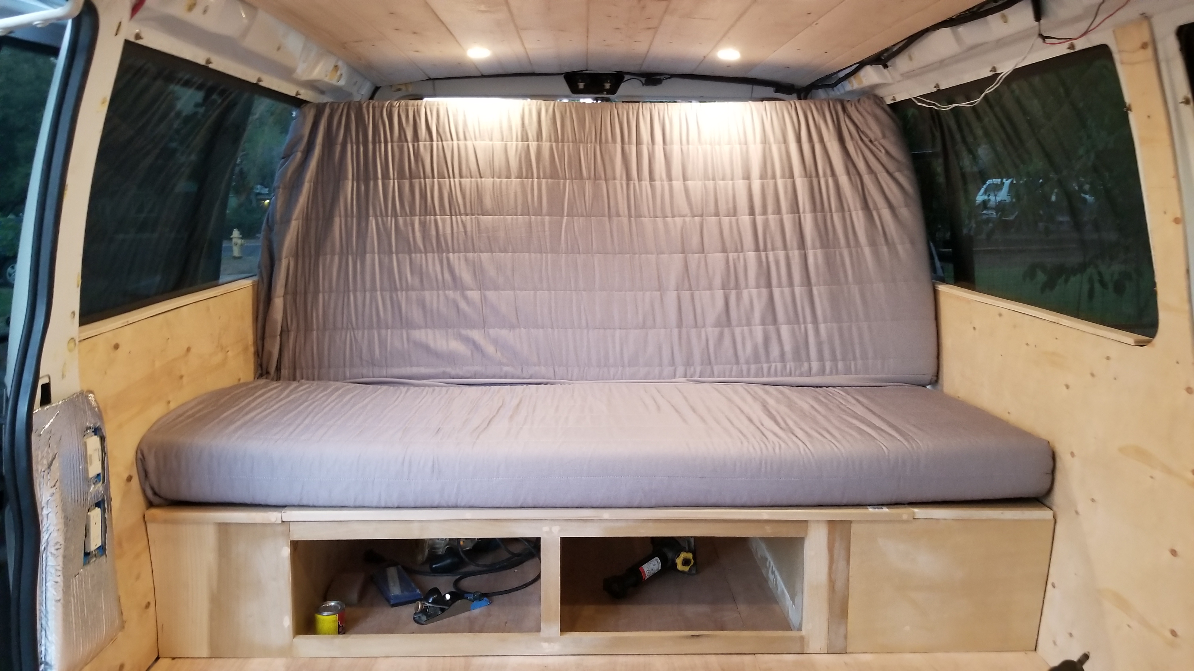
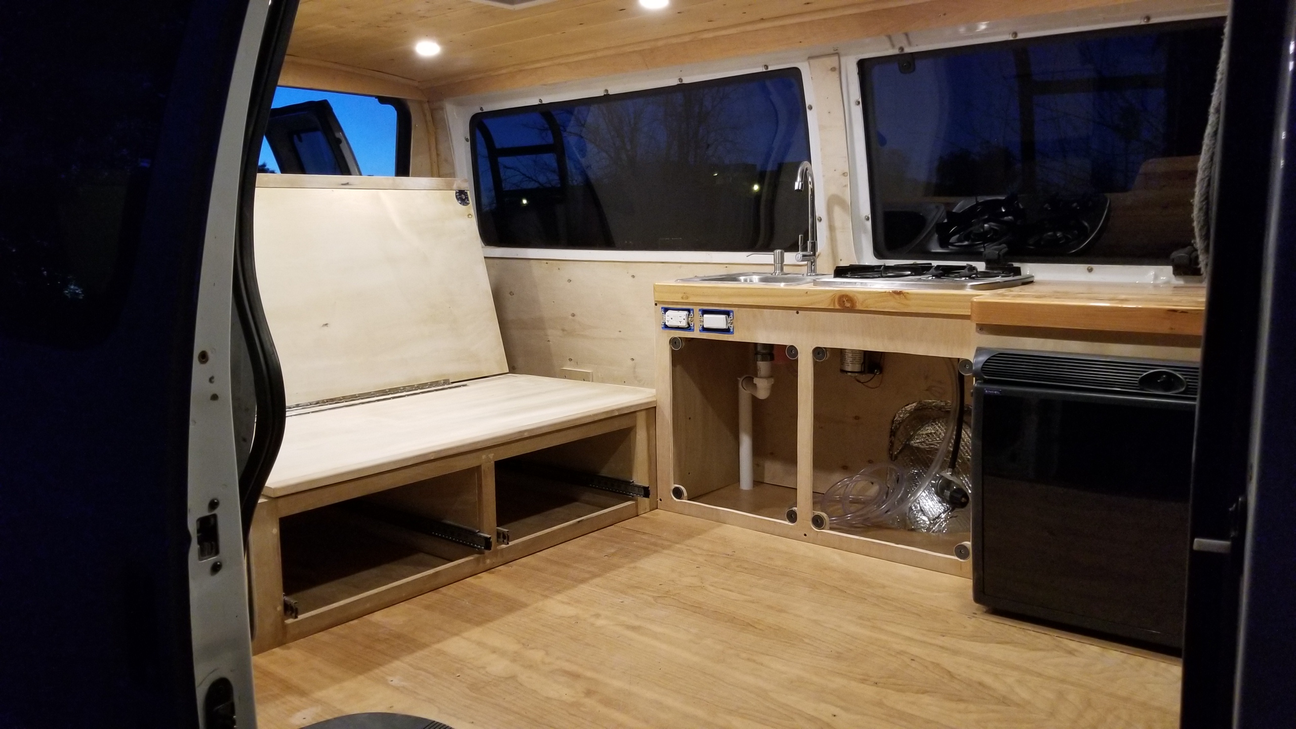
Remember how I said nothing is flat inside the body of a Ford E350 van? This is when it really matters! You want to build a bedframe that is flat; however, you are building on a curved surface. I first built the basic ‘H’ shape of my bed then shaved the bottom down until it sat flat on the floor. Once that step was done I could start building the rest of the bed/storage on this flat base. I chose to have a side-to-side bed (I am 5’7”) that was low enough to the floor that I could still sit up in it and use as a couch (remember to account for your mattress thickness). I also wanted it wide enough to sleep two people. These parameters drove my dimensions of the bed.

Tools/Materials used:
Procedure:
  1. Take measurements of your van, and cut your ‘H’ shape to the height of your bed (with cover and mattress taken into account of course).

  1. Drill bore holes and countersinks for your screws. Screw it together (make sure it is square! 90 degree corners) and place in the back of the van. Your van isn’t flat, just come to terms with it. Once in place you’ll want to shave away the wood in the middle of your ‘H’ shape until it sits flat.
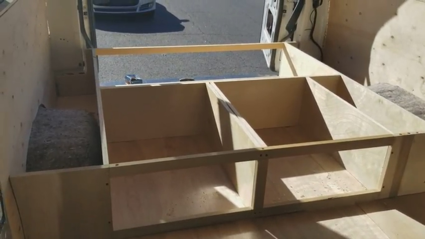
  2. Once flat, cut your face boards out of hardwood (I chose hardwood as it can be sanded down and painted for a finished look). Cut your runners to create openings for your drawers. Ensure everything is square and sitting flush in your van.
  3. Once your frame is complete, screw mounting blocks into the floor and then screw your frame to the mounting blocks. I used wood as it was readily available. I am sure you could use metal brackets. At any rate make sure it’s good and secure so your bed doesn’t go flying across your van when you stop!
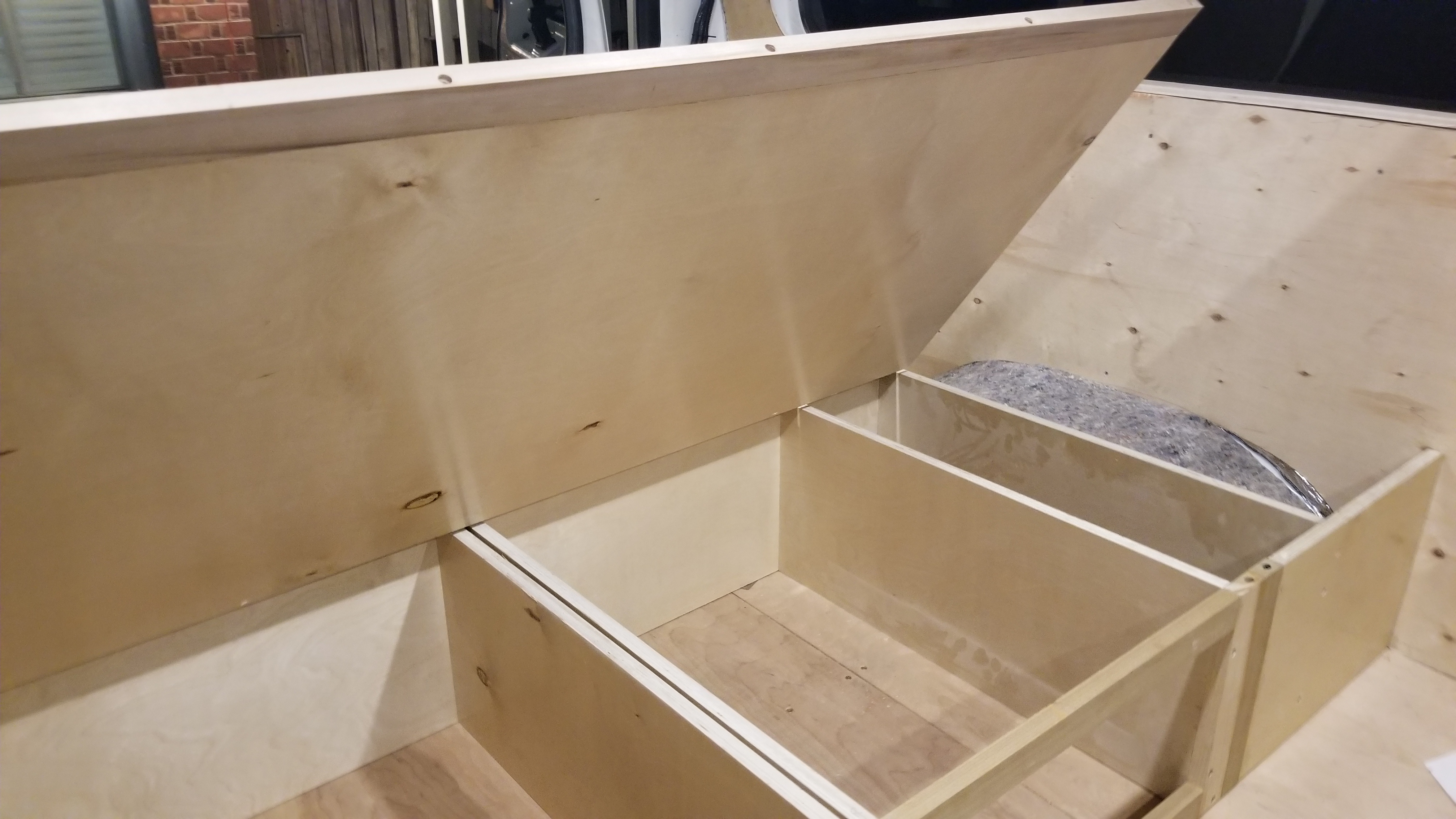
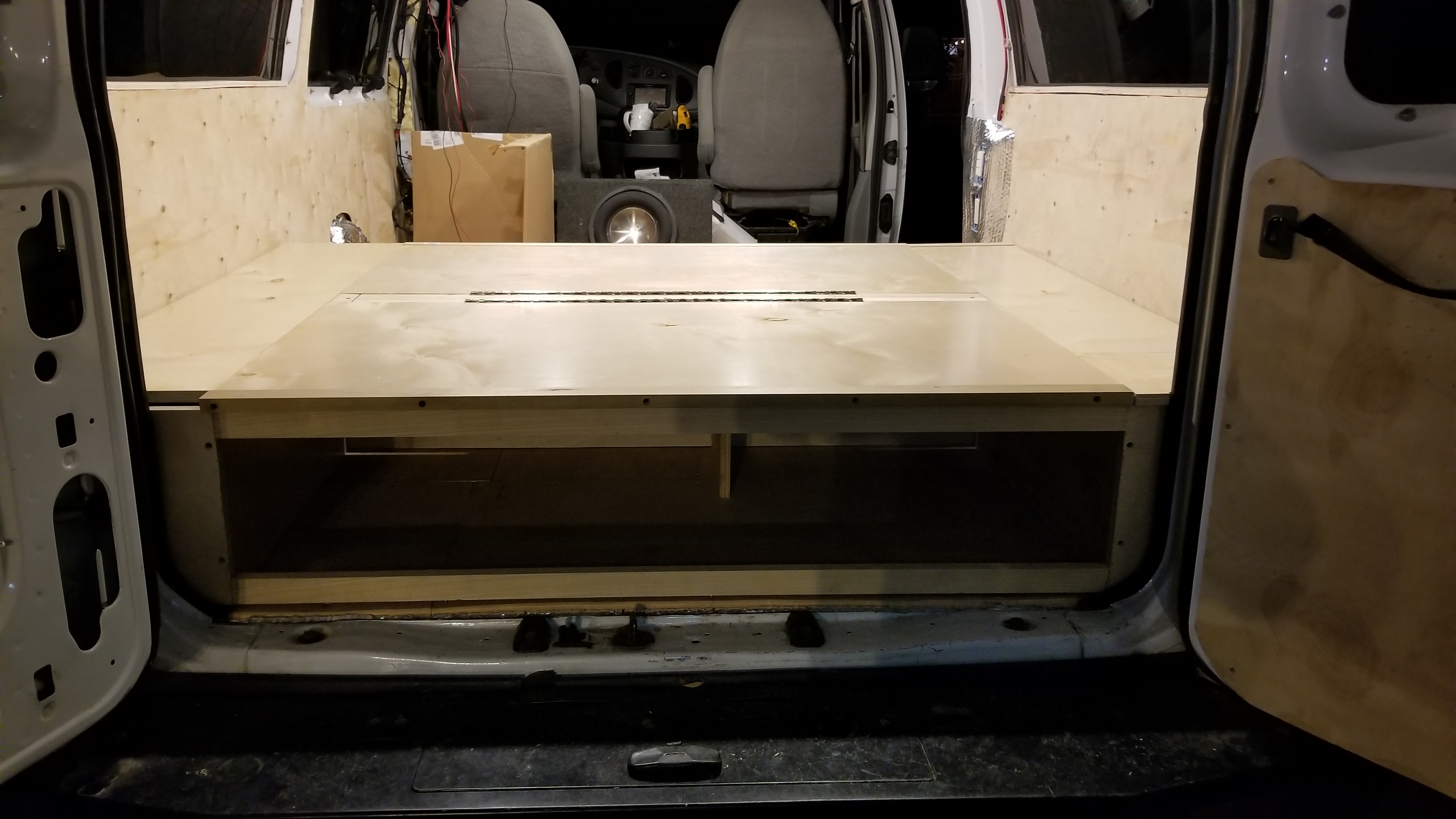
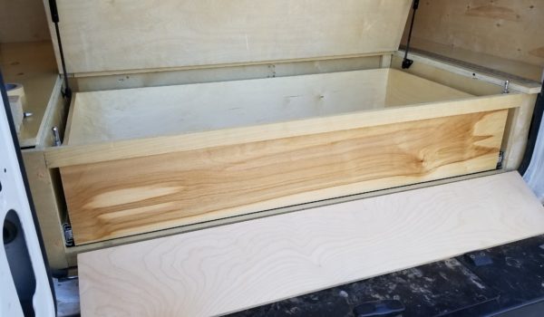
  4. Now it’s time for the top of your bed! I opted to have lids that opened like a chest and swiveled on piano hinges. This gave me access to the storage below without opening the drawers in the front/back but also gave me the ability to make the bed into a couch with the aid of two air shocks (rated at 200 lbs each). I cut a central strip for mounting the two lids and screwed it to the center piece of the ‘H’ shape. Then I cut both lids, laid them down flat, attaching them with piano hinges to the central strut.
    • Video: https://youtu.be/iyKcVvZL-8g
    • Front view! Front lid is on.
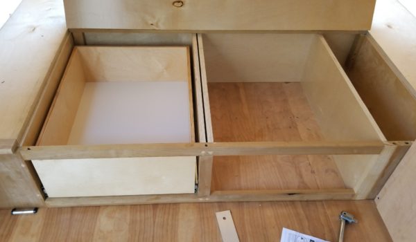
      Looking into the little cubby holes
      Lid will lift for top access to cubbies and drawers
  5. I then cut the side covers for the areas that would not be covered by the lids. The side storage I cut to size using the lids and van walls to keep them in place (no actual attachment, just laid on top). I cut a hole in the top to manually pull for access. I split the difference of the legs of the ‘H’ between the side covers and the two hinging lids to ensure they both had surfaces to rest on when closed. I cut small blocks and screwed them to the wall as a support stopper for these side covers.
  6. I ended up cutting a flat strip of hardwood for the edge of all the lids and screwed it into place from the ends. I did this to keep a clean finish once sanded and painted.
  7. I then installed the air shocks for the back lid and two hood latches. This took some adjusting, but once in position they worked great! You can accomplish this “couch mode” by rigging up a couple of pieces of wood for struts to hold the back lid up. Warning: The shocks will put some decent forces on your bed frame, make sure it’s sturdy or it will rip your lids from their hinges or shift your frame making the perfect lids you cut no longer fit correctly. I went back and beefed my frame up for this reason.
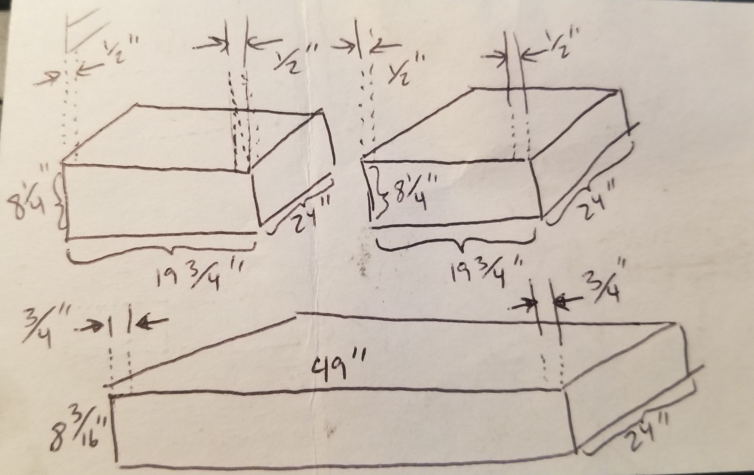
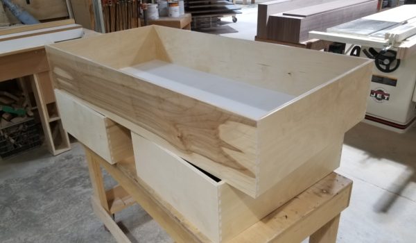
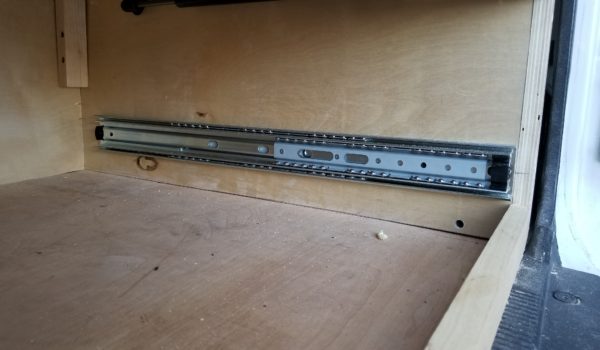
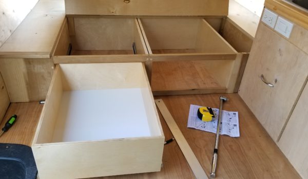
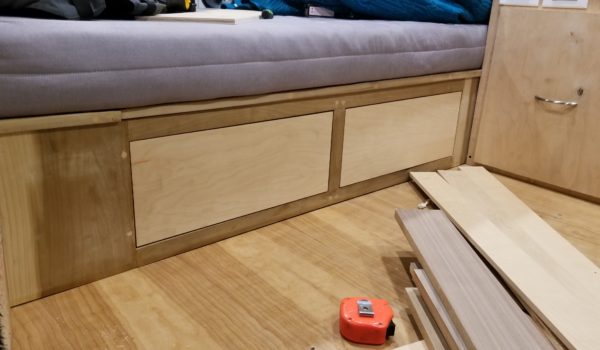
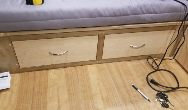
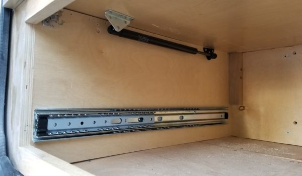
  8. Install your drawers – I bought my drawers custom made, I provided the dimensions of the holes I had designed for my three drawers and gave the dimensions of the sliders I purchased and picked them up when they were done! I really didn’t want to play around with trying to make perfectly square drawers so I outsourced this to my friend Sam’s dad (thanks Peter Gallen!). Once I had the drawers I installed them with sliders that I purchased from Home Depot (the sliders come with installation instructions). Once installed I (Peter actually) cut facer covers for all three drawers and screwed them in from the back to give the closed drawer a flush look (don’t need to be snagging everything on the edges of drawers).
    • Measure your drawer hole, then subtract the size of the sliders from the side to get your drawer size.
    • Video: https://youtu.be/ZNaGEtvXih4
      • Be a bum and get someone professional to build you some stellar drawers (Thanks Peter Gallen!)
  9. Stain your drawer facer boards and install your handles. I installed sleek handles on the front (facing the living space) that wouldn’t snag. I simply cut an elongated hole in the large back drawer in the back that I could just grab by hand (no handle needed).
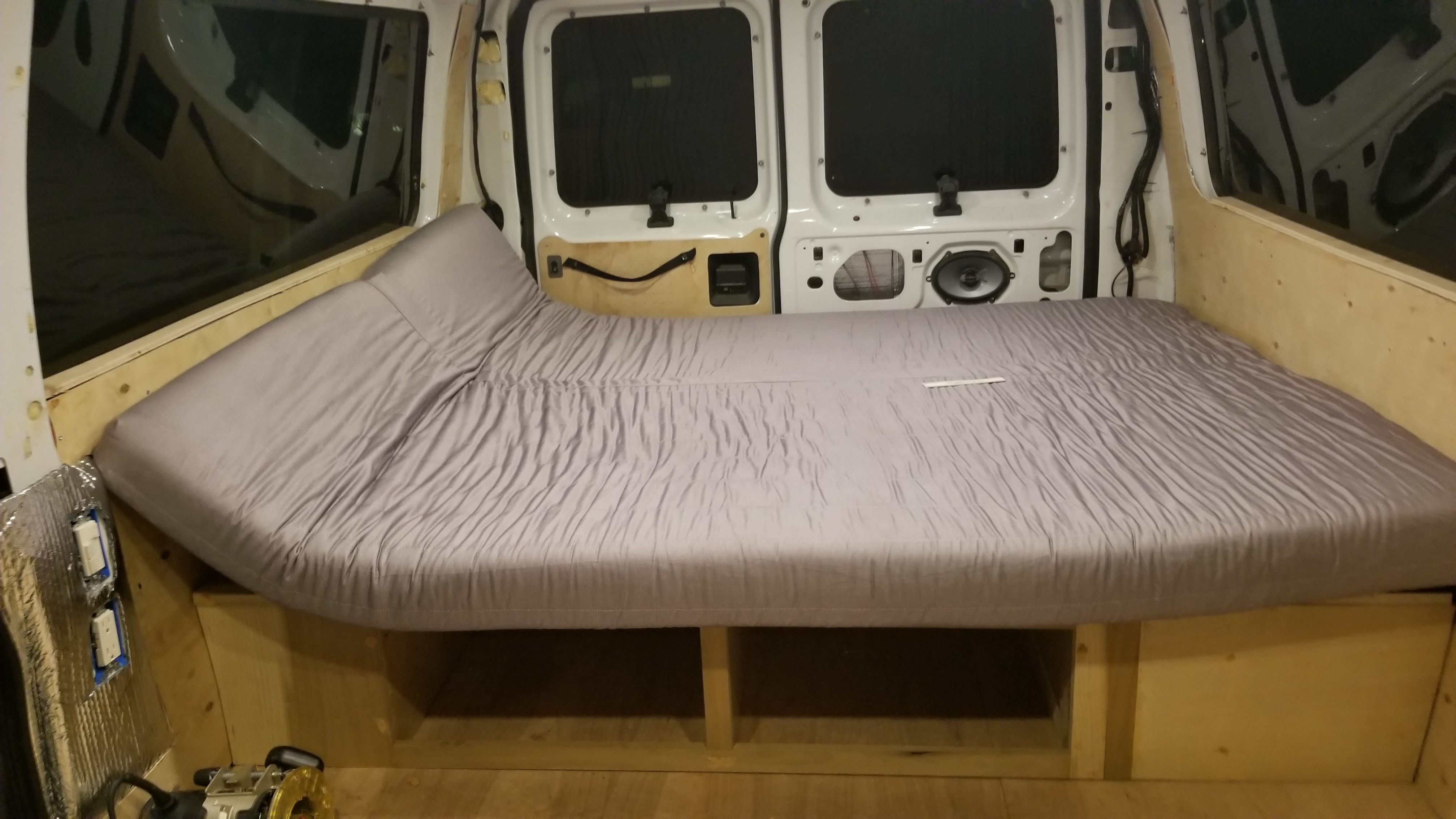
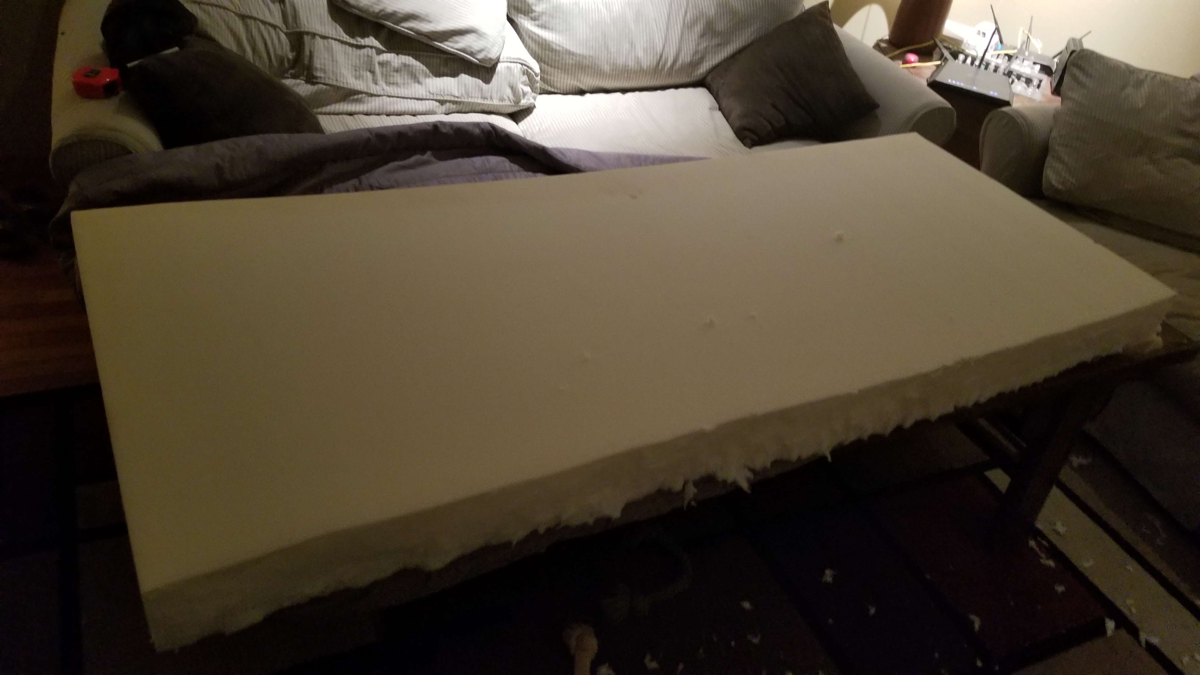
  10. Cut your futon that you bought from IKEA down to fit your bed frame. I removed the foam blocks from inside the futon and cut 6” off the height and 3” off the side to side to fit. I took my futon cover to an awning company to be boxed up to fit the cut-down size of the foam pieces.
  11. Now that you’ve pulled your hair out getting this thing into place, screwed down, and operational, just have a break and drink a beer . . . this may be the most important step for your sanity!


Share

CamperVan Build – Step 8: Build Storage/Sink Area

Share

Step 8: Build Storage/Sink Area

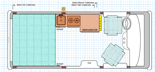
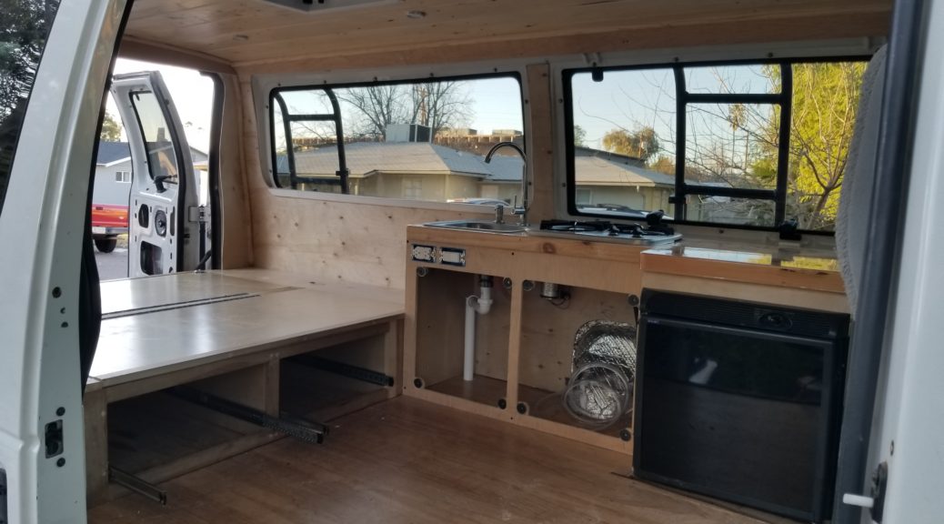
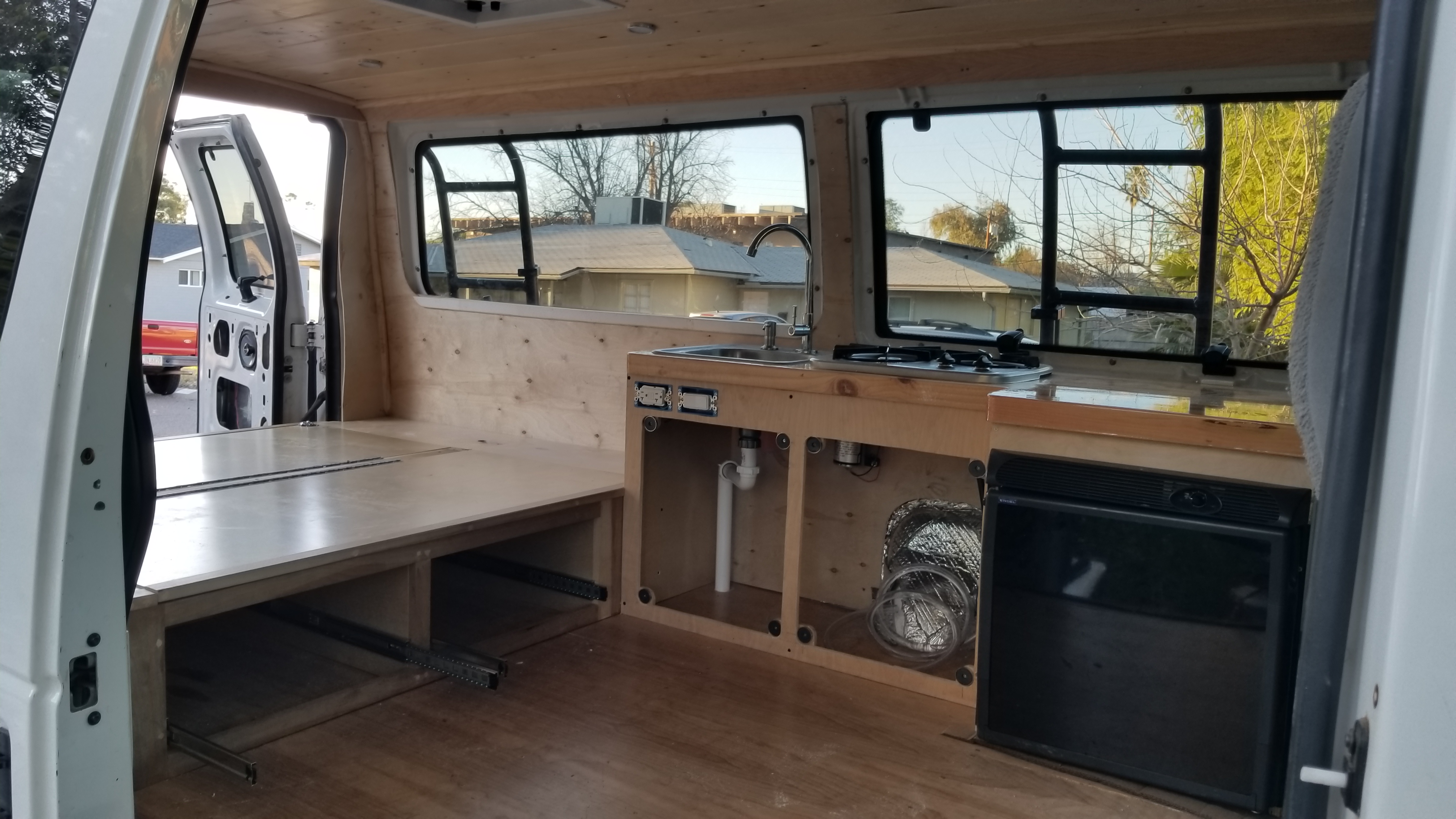
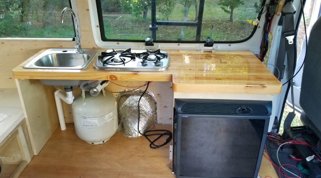
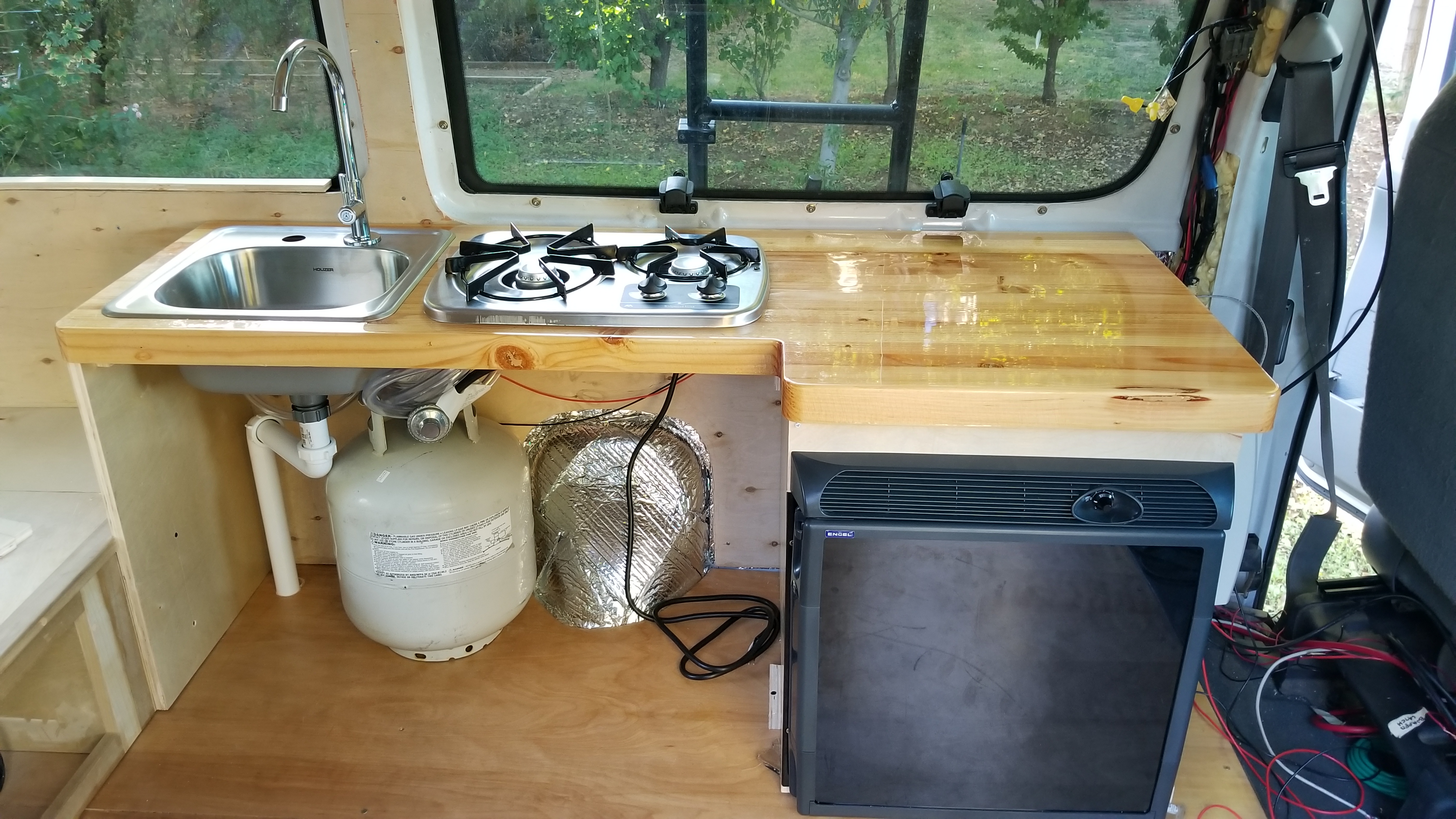
Endless options and different ways of doing this part; so I am just going to stick to what I did. I built everything around my appliances. The sink, stove, and fridge were allotted to this area. I wanted the counter to cover the top of the fridge and be big enough for my sink and stove. Of all the areas of the van, you will be using this the most when you cook your meals. I opted to have the sink closest to the bed (makes for lazy teeth brushing at night/morning), then the stove in the middle (dimensionally it was close to the sink size (front to back) and I wanted it farther from the bed for safety), and lastly I placed the fridge furthest right (just behind the driver’s seat). I built the countertop around the appliances, then the cabinet to hold it up, cabinet doors were last of course.

NOTE: All appliance installs (including fridge, sink, stove pictured in this Step) will be Covered in Step 9: Install Appliances. 

Tools/Materials used:
Procedure:
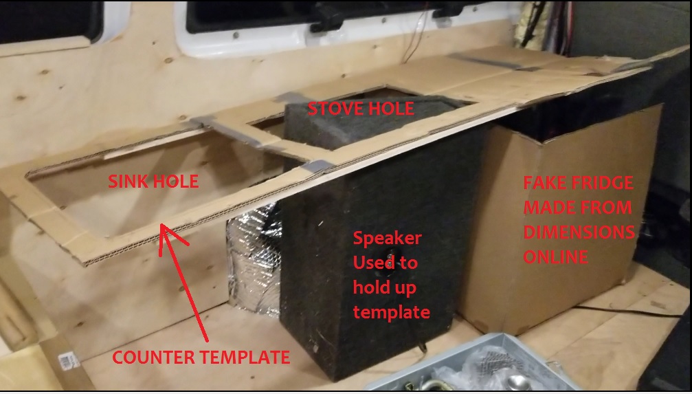
  1. Make a template (I made mine from cardboard), I can’t stress this enough, this will help you so much in not only in the design of your counter, but it will also help you decide what appliances to purchase by understanding the workspace you have to deal with.
    • Cardboard template! Lifesaver
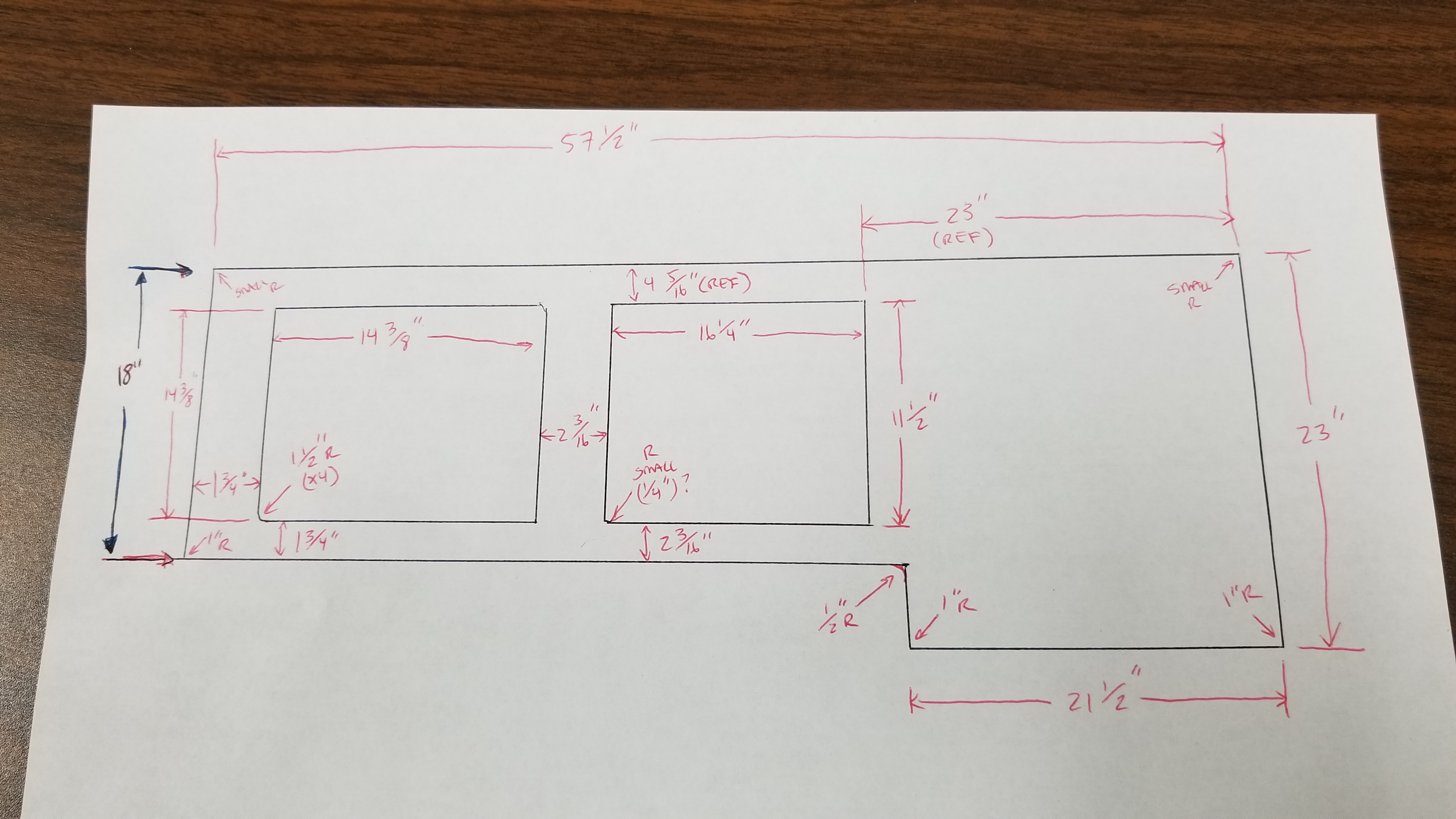
  2. Get your appliances in hand (or just pull dimension from online) and cut your template to the final dimensions making sure everything fits where you want it.
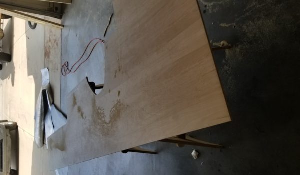
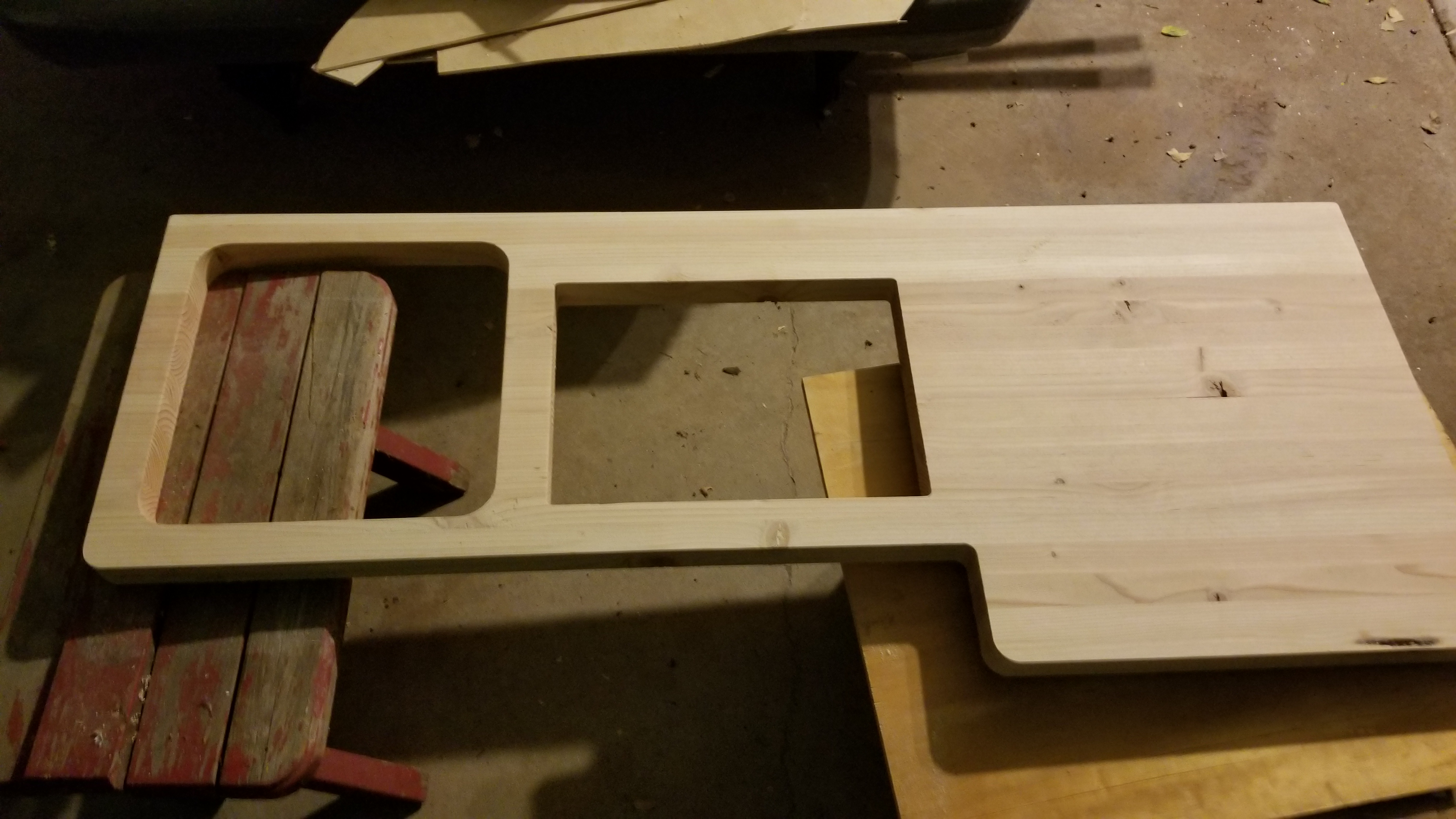
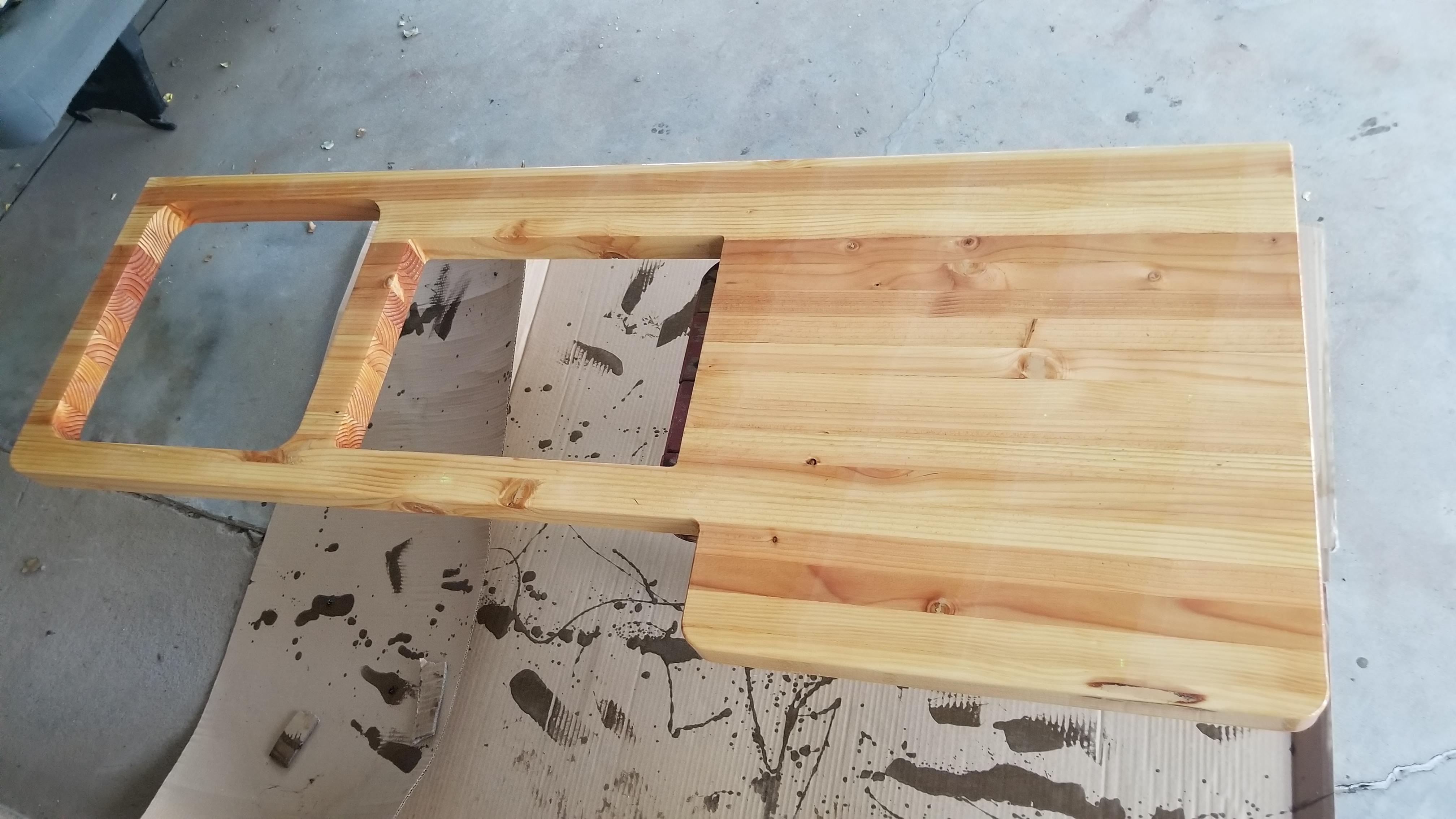
  3. Use the template to take measurements and cut your final countertop. I outsourced this to a guy with a CNC shop who happened to have a chunk of glued together hardwood that was messed up for a customer (and was going to be scrapped). It was the right dimensions for my build so I snagged it at a deal and got the CNC cutting done for free 😉 Right place, right time kind of thing. The countertop was made from strips of pine, glued together, jointed, planed, then cut to size.
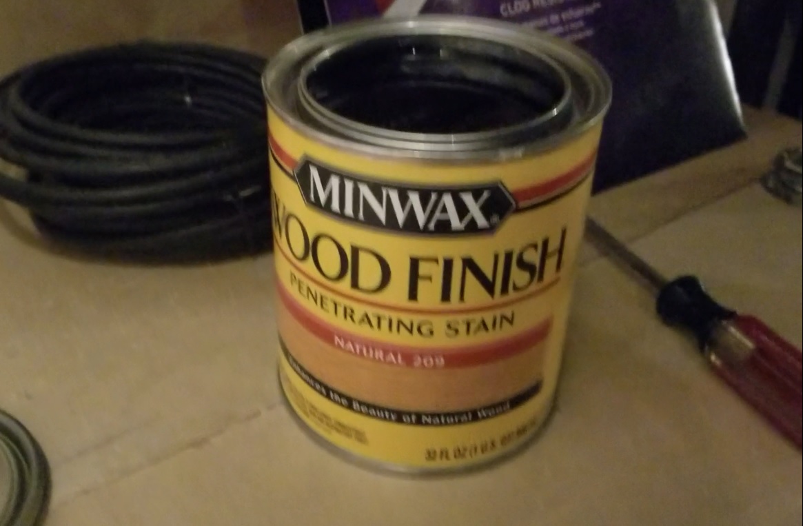
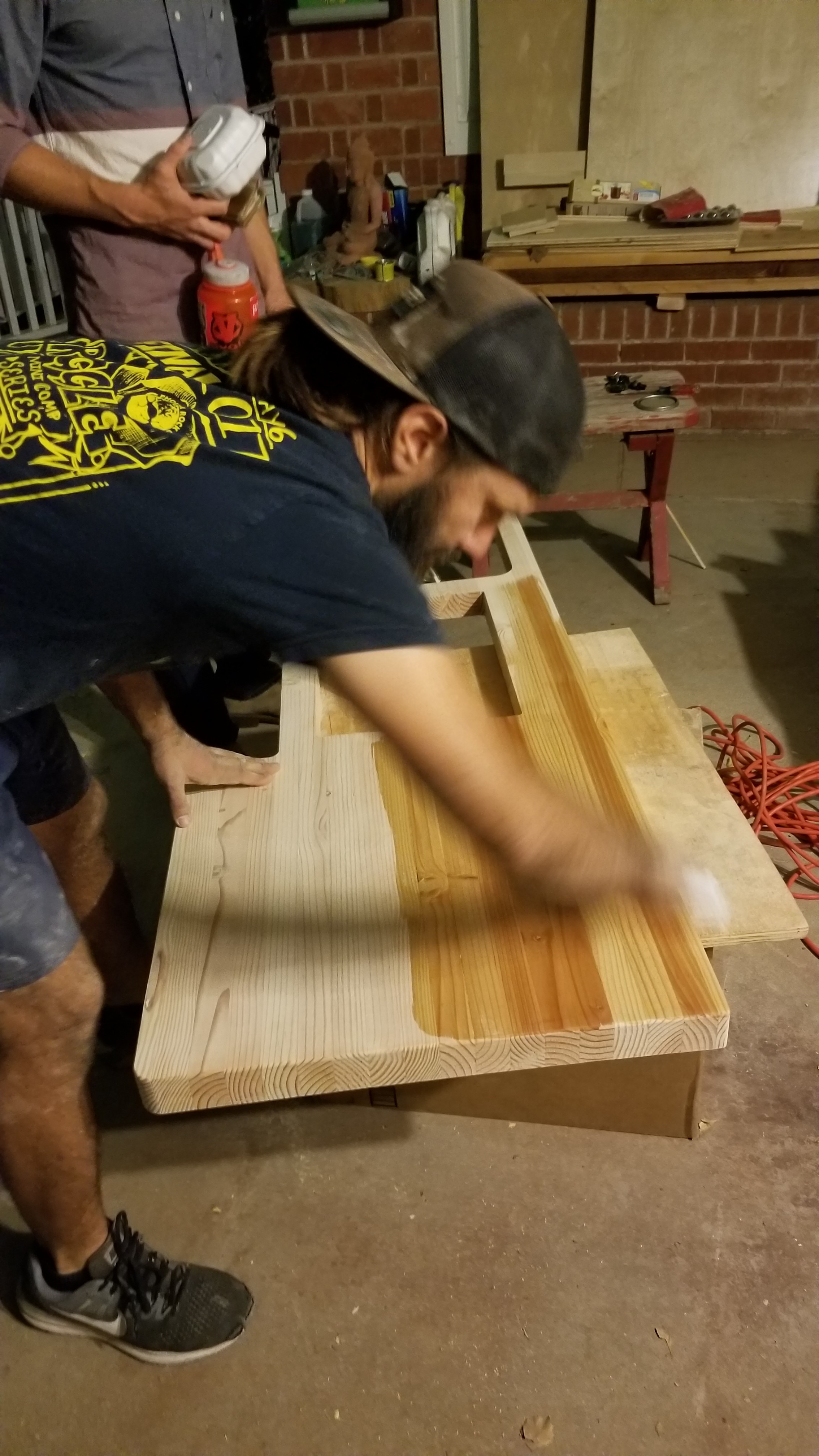
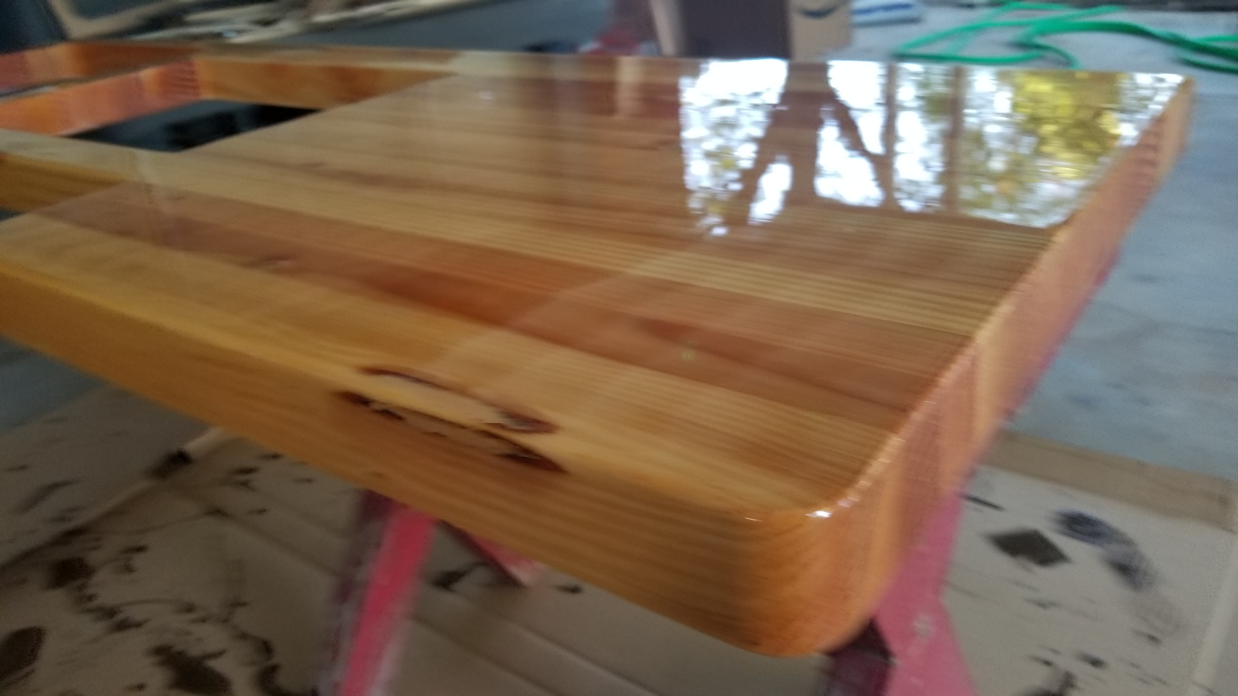
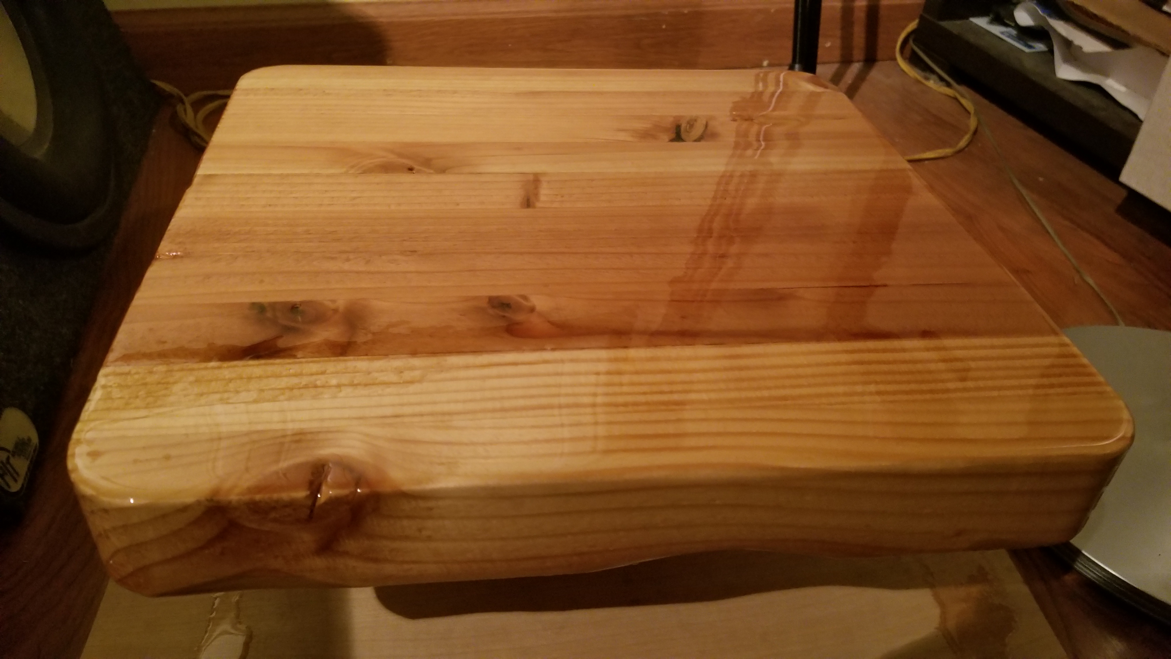
  4. Stain and seal your countertop: I first filled all cracks with wood putty, sanded it down, routered the outer edges, then stained with Natural 209 (that I used on the ceiling). Finally, I sealed it with SuperGlaze Gloss Kit (just follow the instructions on the kit – You get to use a Propane Torch YAY!!!!)
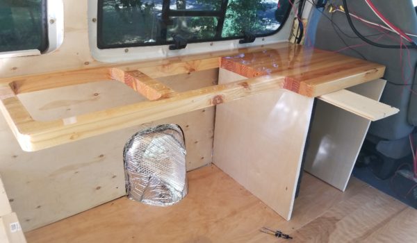
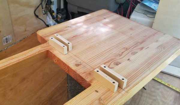
  5. Build the legs for your counter. I used the wall as the back face and cut three legs to size and fit them into place. I put my fridge in at this point to make sure dimensionally that the counter legs fitted around it. Once in place, I screwed the legs to the bottom of the counter using blocks, reinstalled the counter and legs into place and screwed it down to the end of the bed. I then screwed it in place to the floor walls using mounting blocks I cut from wood.
  6. Cover the face of the cabinet. I used ½” plywood (use thicker if you have it for durability),that will be painted later, and cut to size with 2 holes for cabinet access (in hindsight I would use ¾” wood here so I can have more options for cabinet door hinges).
    1. Once installed, cut two holes with shallow blue wall outlet boxes.
    2. Install the shallow blue outlet boxes, and then install a switch into one and a wall 125V outlet into the other.
    3. Wire up the switch in line with your water pump (I cover this step further in the Install Appliances Step).
    4. Wire up your outlet with wires from an extension cord and run the end of the plug near the place where you plan to install your inverter.
    5. Install the plate covers on the outlets.
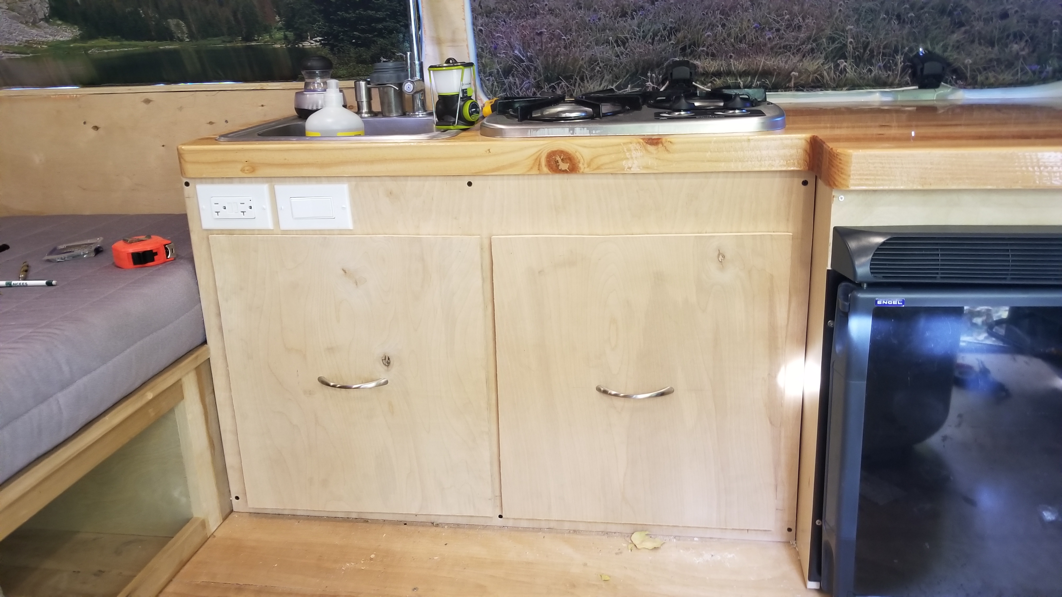
    6. You can see the cabinet face installed here with the Wall Outlet and water Pump switch in place.
  7. Cut the cabinet doors. I used some ½” plywood to cut some lightweight cabinet covers which I fixed into place with magnets (I wanted to remove them later and use them as cutting boards or lap tables). Make 4 magnet mounts for the corners of the cabinet doors and install them on the back of the cabinet face (see video for clarity). Router the outer edges of the cabinet doors and sand down any imperfections.
  8. Stain and seal the cabinet doors with the same stain and sealer as the ceiling, counter, and drawer faces.
  9. Affix your handles to the cabinet doors (I used the same handles as the front drawers beneath the bed).
Share

CamperVan Build – Step 9: Install Appliances.

Share

Step 9: Install Appliances.

It’s time to get serious (as if you weren’t already!)! This is where you put in all those high dollar expenses you dropped on appliances . . . oh yeah, and the part where you CUT A HOLE IN YOUR ROOF (I cried a little, just being honest)! Fantastic  fan, fridge, sink, stove, water pump, time to throw it all in there.

Tools/Materials used:

Procedure:

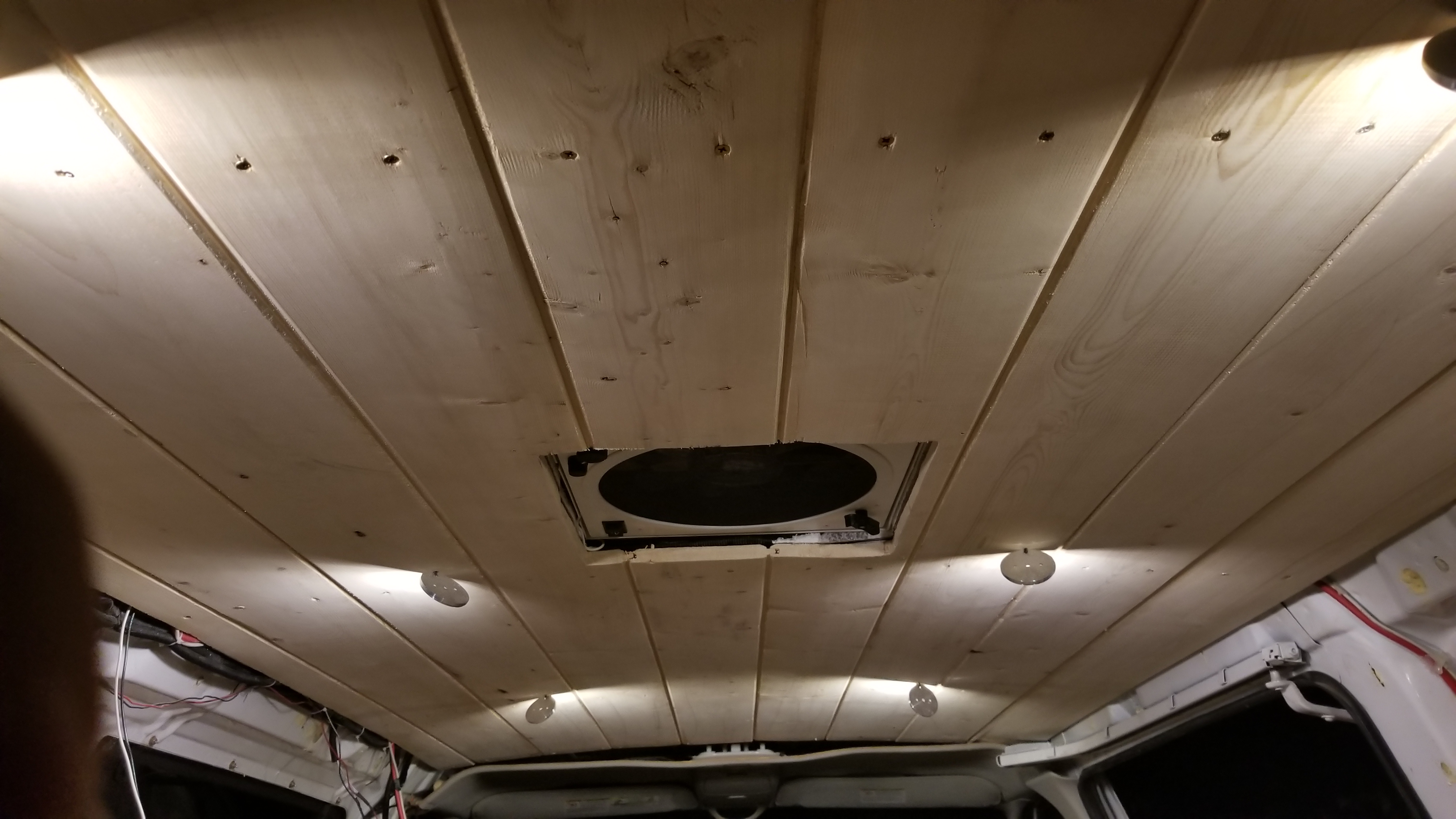
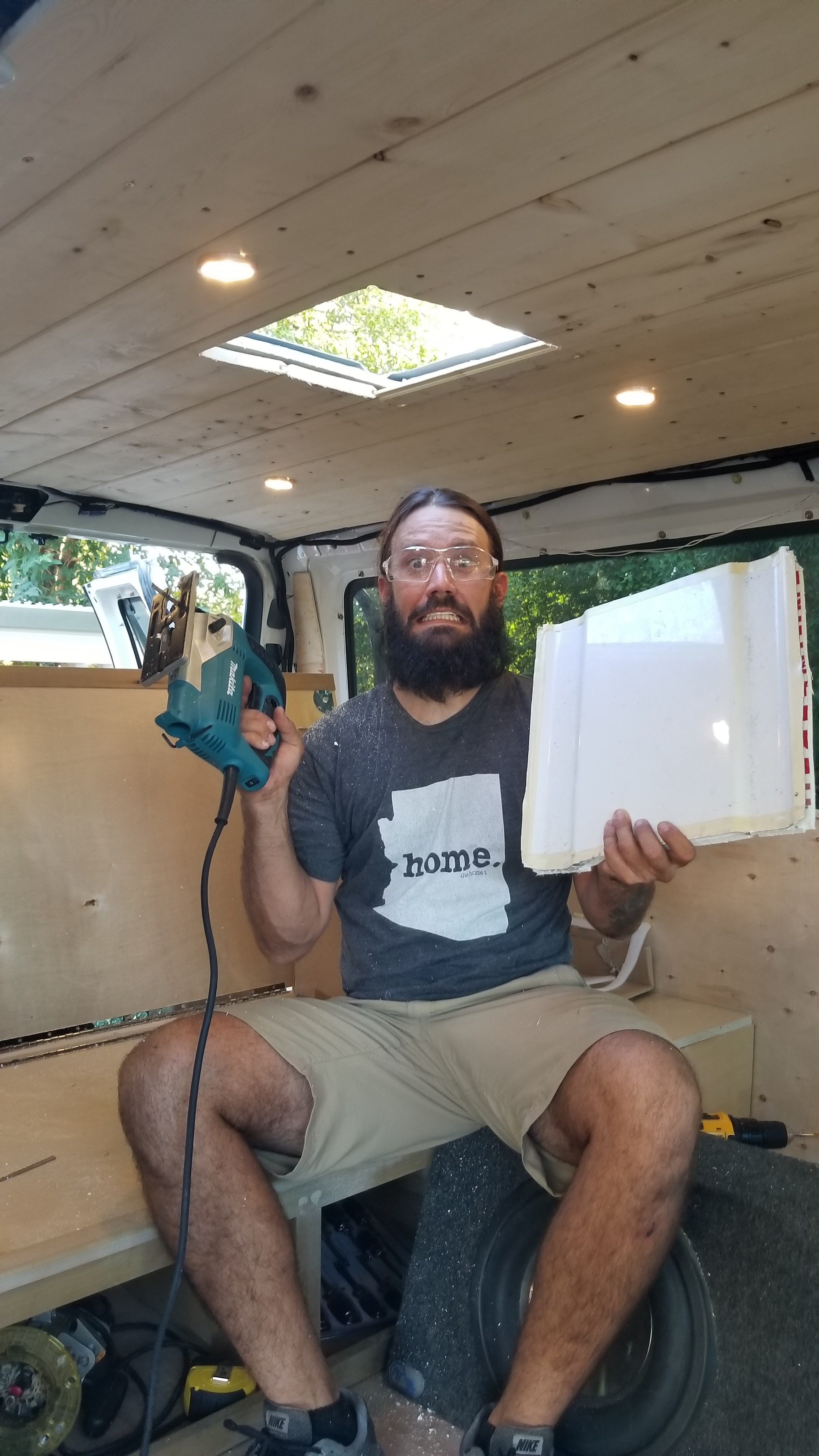
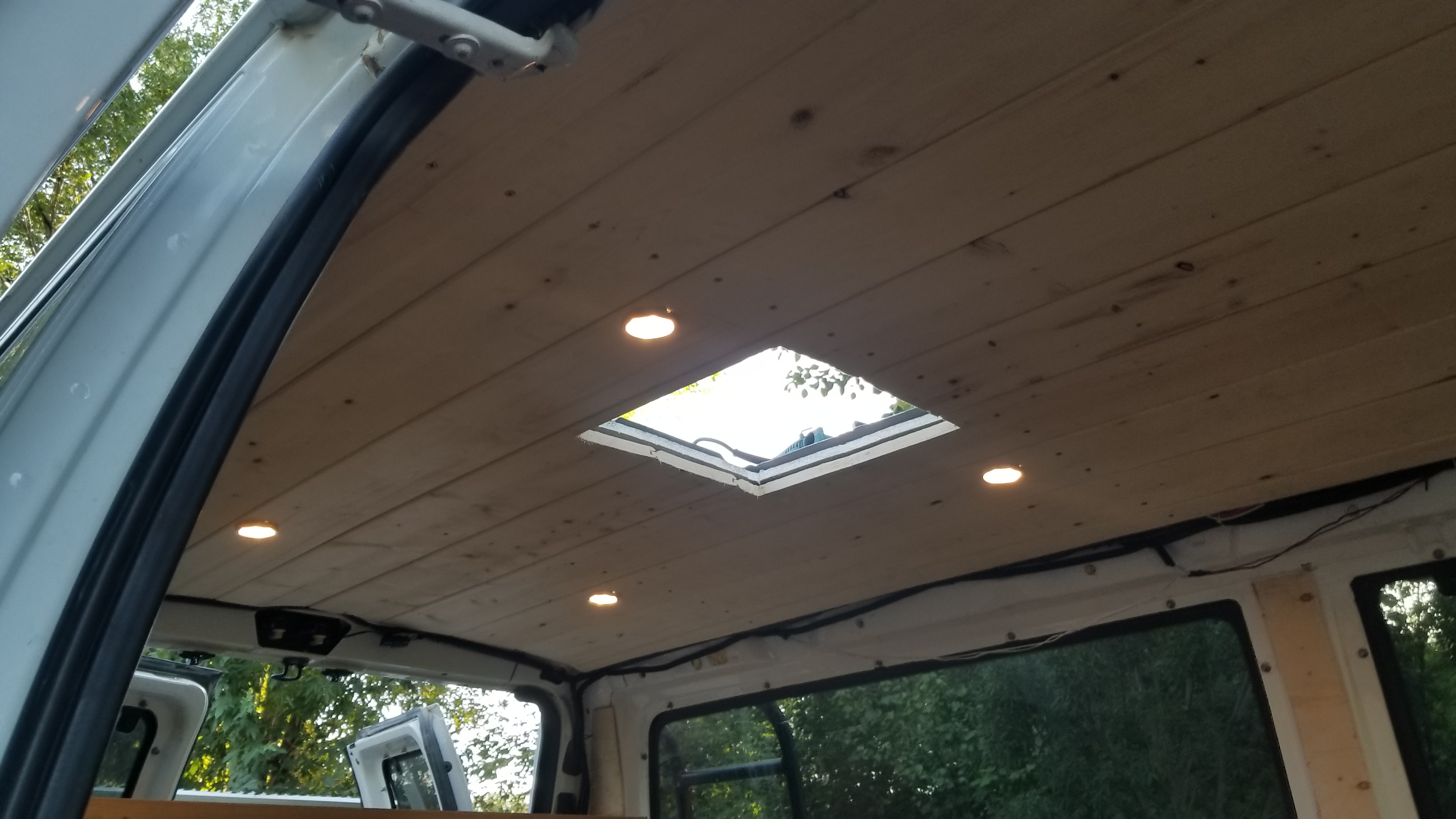
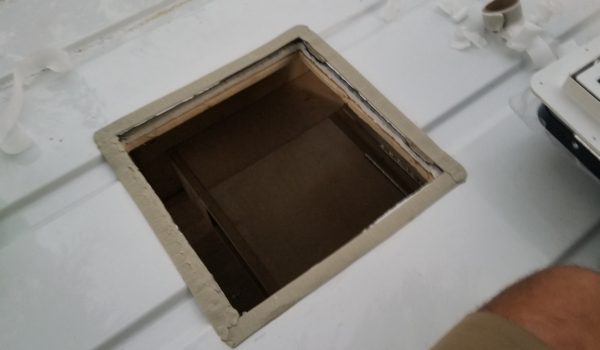
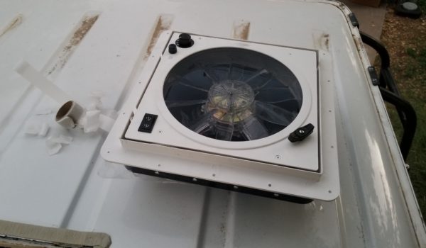
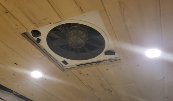
  1. Cut a hole in your roof! I knew right about where the cross bar support for of my roof were and I wanted to get my ceiling in first before cutting my fan hole (I did this so I wasn’t building around the fan when I installed my ceiling, forcing those tongue and groove boards into place was hard enough, just imagine working around a hole and aligning perfectly). It was a gamble, but it paid off. Mark your ceiling where your fan will go, drill 4 holes at the corners of your square, mark the lines on the roof (inside and out) and cover the lines with tape (the tape will help hold onto the metal and wood shavings and keep a smooth cut). Use a JigSaw and cut that bad-boy out! I played it pretty close to the wiring that I installed right before the insulation went in, but it worked perfectly.
  2. Install your Fantastic fan (use the instructions that come with it, don’t forget to putty and calk seal for a water tight seal. I oriented the opening of my fan towards the rear of the van so I wouldn’t accidentally rip the fan cover off if I forgot to close it properly and drove off. Go ahead and solder the fan’s wires into the wires you put into place before insulating the ceiling.
      • Clean all surfaces and get that putty going! This is crucial to having a leak free fan!
    • Install Video 1: https://youtu.be/Uze1B9_vKEw
    • Install Video 2: https://youtu.be/EABCH8bVfdY
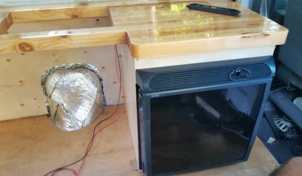
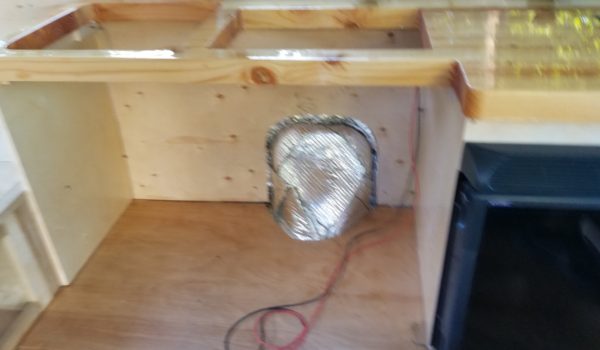
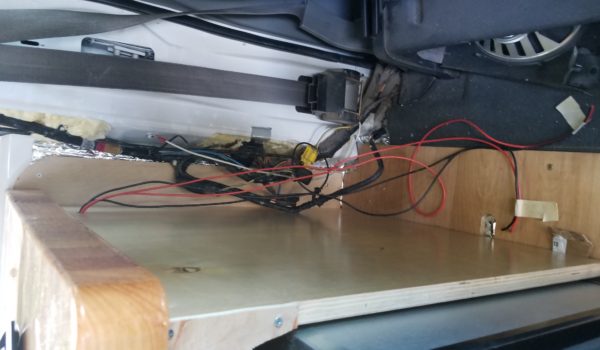
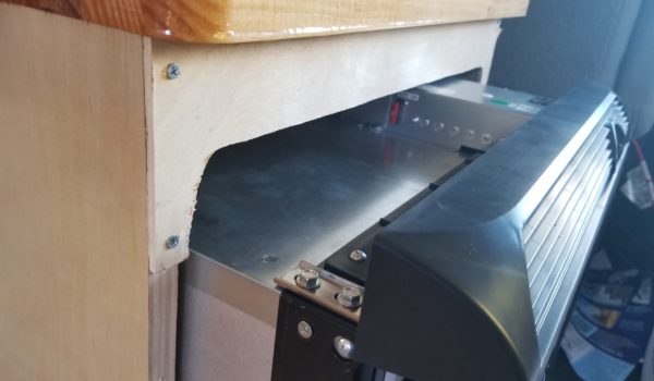
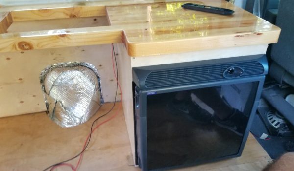
  3. Install your refrigerator. First I drilled a ½” hole in the back right leg of the cabinet high enough to clear the fridge (This hole will be for the fridge wires). Scoot the fridge into place and screw it to the face of your cabinet. Taking a measurement, I cut a custom piece of wood to cover the hole that was left below the counter and above the fridge (you will paint this later). Pull the fridge out a bit, run your wires through the hole in the cabinet to the fuse box area. Install the custom wood piece cut and put the fridge back into place.
      • Run wires through the side hole you drilled
    • Video: https://youtu.be/z0z3IhPkf1MRemove the cabinet covers and the cabinet face cover to make working under the cabinet easier.

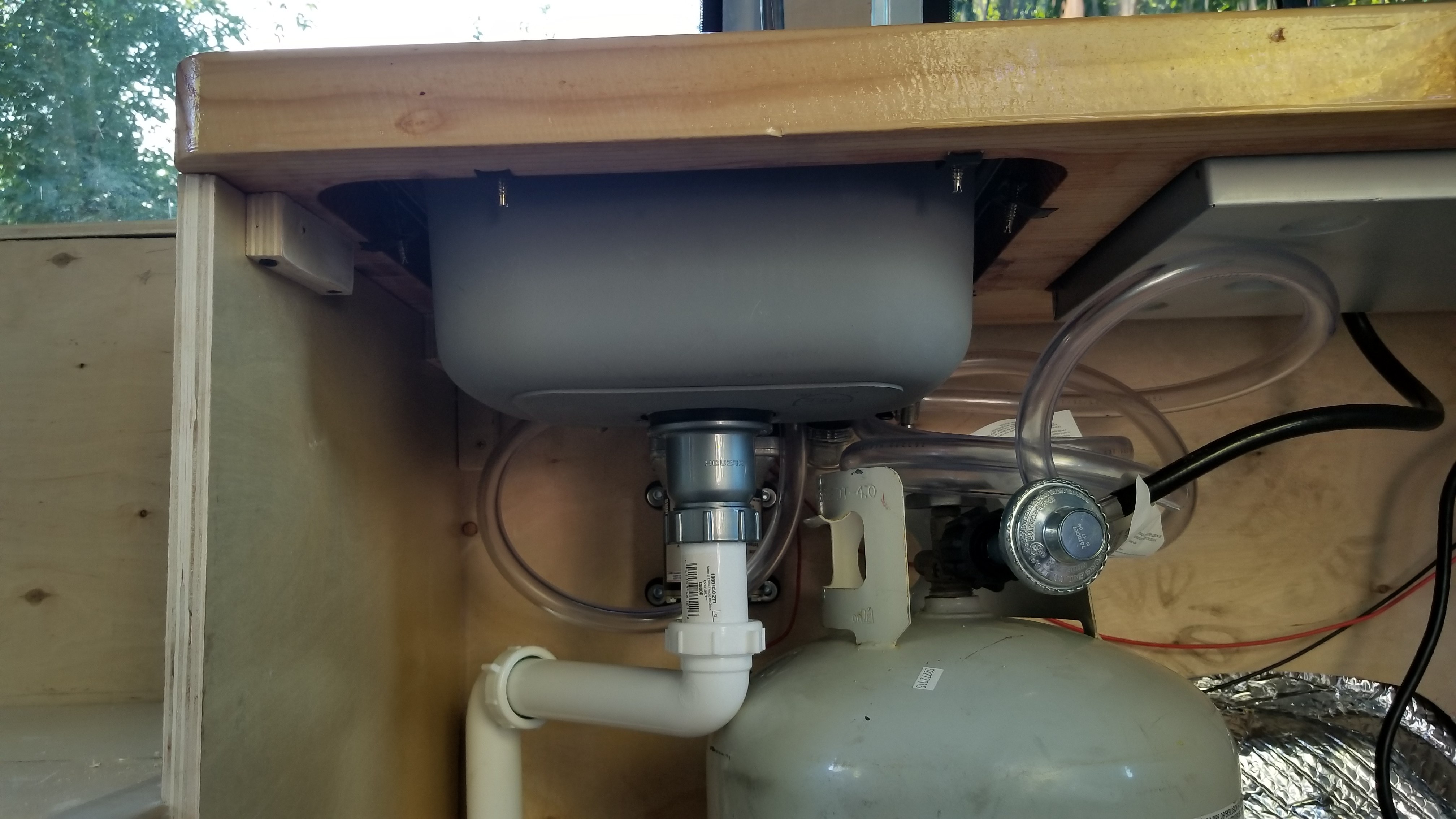
  4. Install your sink (follow instructions that come with it). Install sink drain. Install sink drain piping with the 2 kits you bought. Finally cut a hole through the floor of the van and routing the piping kits until it fits. Connect your water tank to the faucet with th 1/2″ hose and hose clamps. (Video below)
    • Place sink in with manual instructions.
    • I piped the sink straight through the van floor to the ground. I use Eco safe soap, and just water goes down the sink.
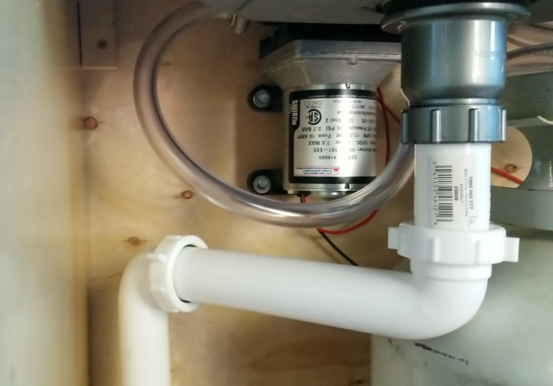
  5. Install the water pump. I attached the pump to the back wall of the cabinet with four screws. Run the feed hose from the sink to the pump outlet and the hose from the pump inlet to your water tank. I have been using a temporary/portable seven gallon water tank which I drop the feed line into. I will eventually install a permanent larger tank inside the van (outside the van would run the risk of freezing water and busting lines). Run the wires for your water pump by drilling a good 1/2″ hole through the cabinet center leg in the back, I made sure it is high enough to be above the refrigerator on the right. Run the wires through the cabinet to the fuse box area. Run the 1/2″ hose from the pump to the sink input tube and to your water tank. Tighten everything with hose clamps. (Video below)
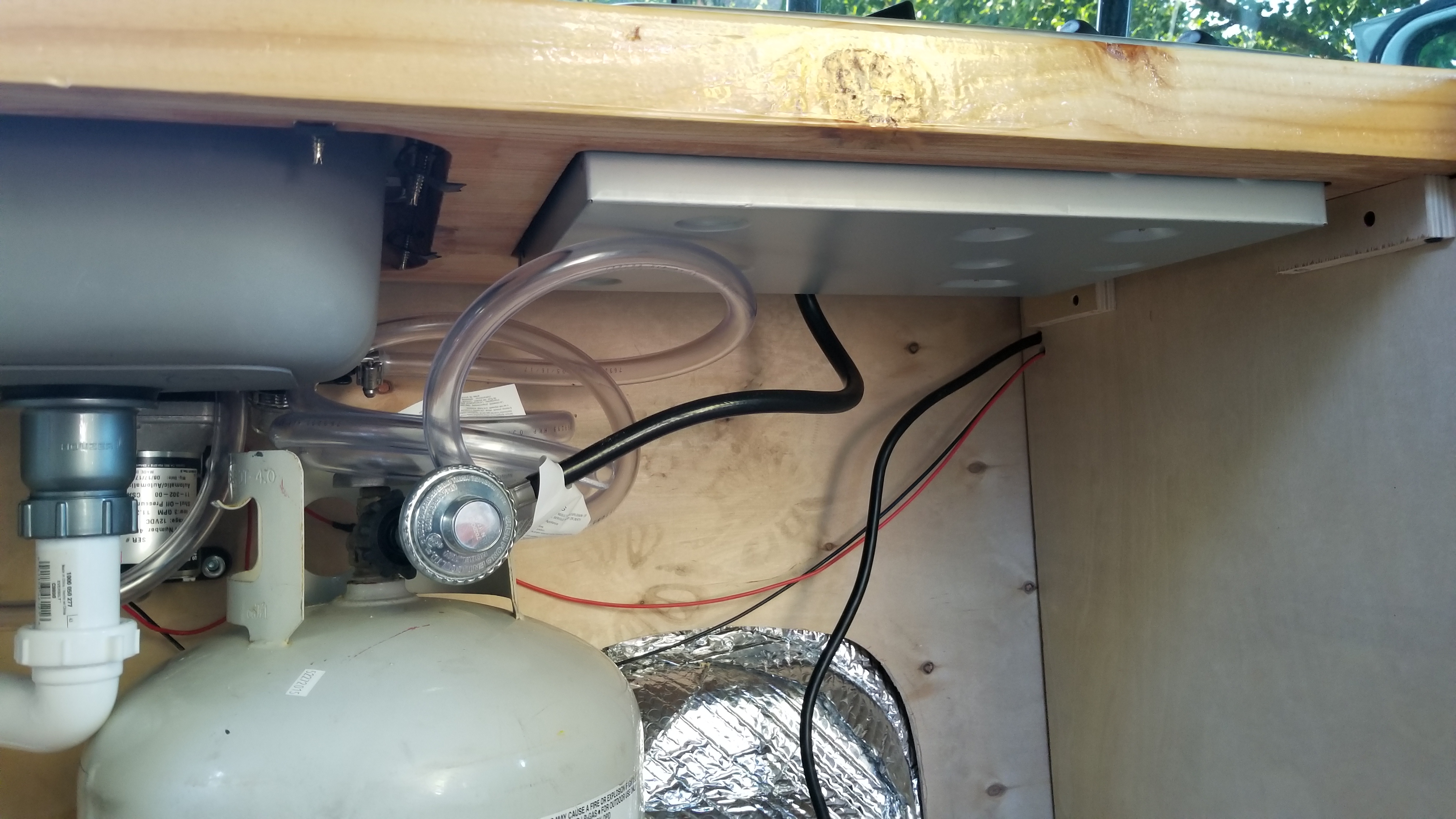
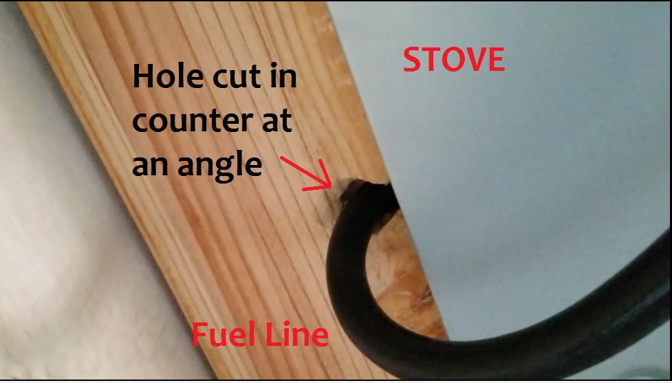
  6. Install the stove (follow the instructions that come with the stove). I chose a propane stove and bought an extension line that hangs down inside the cabinet. I have a flat bottom propane tank which I use to fuel my stove that sits inside the cabinet (make sure you close the valve after use and run your Fantastic fan while cooking). (Video below)
    • Install stove
    • Modify the counter to adjust for the fuel hose
Video: Sink, Stove, and Water Pump Install:
Share

CamperVan Build – Step 10: Wire it up.

Share

Step 10: Wire it up.

It’s time for the part that most people are afraid of, electricity! By this point all the ends of the wires for your appliances and lights should be hanging around the designated fuse box area. I will do this Section in three parts: 1) Basic Electrical Theory, 2) Basic Circuits, and 3) Putting Theory to Work (the install).

Click for Basic Electrical Theory Details

Basic Electrical Theory

Electrical Analogy: I want you to imagine that your batteries are buckets which can be filled with water. The water in this metaphor is current (or flow of electrical energy that appliances require to operate). Once your buckets are empty, you are out of electrical energy and cannot run any electronic appliances until you fill them up again. The buckets are just an easy way to understand that batteries can store electrical charge at a limited capacity dependent on what kind or battery you purchase.

Image result for lifeline batteries

Batteries (buckets) – Choosing your batteries is a great starting point for designing your electrical system. You need to try and imagine you are in your van and all charging is off (no sunlight, no engine or generator running) and think about what all appliances you will use and how long you will use them. Every appliance (water pump, Fantastic fan, LEDs, plugin appliances) has a power rating. For example LEDs require a 12 Volt source and a power rating of 12 Watts. Don’t let words like Watt scare you, this is very very simple math and here are the three equations:

  • Eq1: V = I*R; where V=Volts, I=Current (measured in amps), R=Resistance
  • Eq2: P=V*I; where V=Volts, I=Current (measured in amps), P=Power (Measured in Watts).
  • Eq3: Pin = Pout; where Pin in power input, and Pout is Power output.

So if an appliance gives you a Voltage and Power rating, you can easily figure out how much current the appliance requires by rearranging Eq2. I=P/V. So in our example, the LEDs require a 12 Volt source and a power rating of 12 Watts. Thus the current I = 12 Watts/12 Volts = 1 amp. So the LEDs require 1amp at maximum output (they may pull less current if you have them on a dimmer).

What you need to do is add up the current all your appliances will use, and how long you plan to run them (in hours). So let’s pretend you plan on leaving your lights on 24-7. The 12 Volt LEDs will use up 1amp for the duration of 24 hours. You would require at least: Amp*Hours = 1amp*24 Hours = 24 amp hours.

Deep cycle batteries (buckets) are rated in AH (Amp Hours). So your 12 Volt battery will be rated somewhere in the neighborhood of 200 Amp-Hours which means that in a perfect world the batteries could deliver 200 amps over 1 hour, or 20 amps for 10 hours, or 2 amps for 100 hours, ect. Warning! Make sure to get Deep Cycle batteries, these are designed to be charged and discharged many times, they are different from starting batteries.

Sum up all the appliance currents and the hours you intend on using them to “size” your batteries.

  • Puck LEDs: 1amps * 3 hours = 3 Amp Hours
  • LED Strip: 5amps * 0.5 hours = 2.5 Amp Hours
  • Water Pump: 2.7amps * 0.5 hours = 1.35 Amp Hours
  • Fridge: 2.7amps * 8 hours = 21.6 Amp Hours
  • Fantastic Fan: 1.5 amps * 1 hours = 1.5 Amp Hour
  • Phone Charger: 1.67 amps * 4 hours = 6.68 Amp Hour

Sum up all appliance Amp Hours = 36.63 Amp Hours.
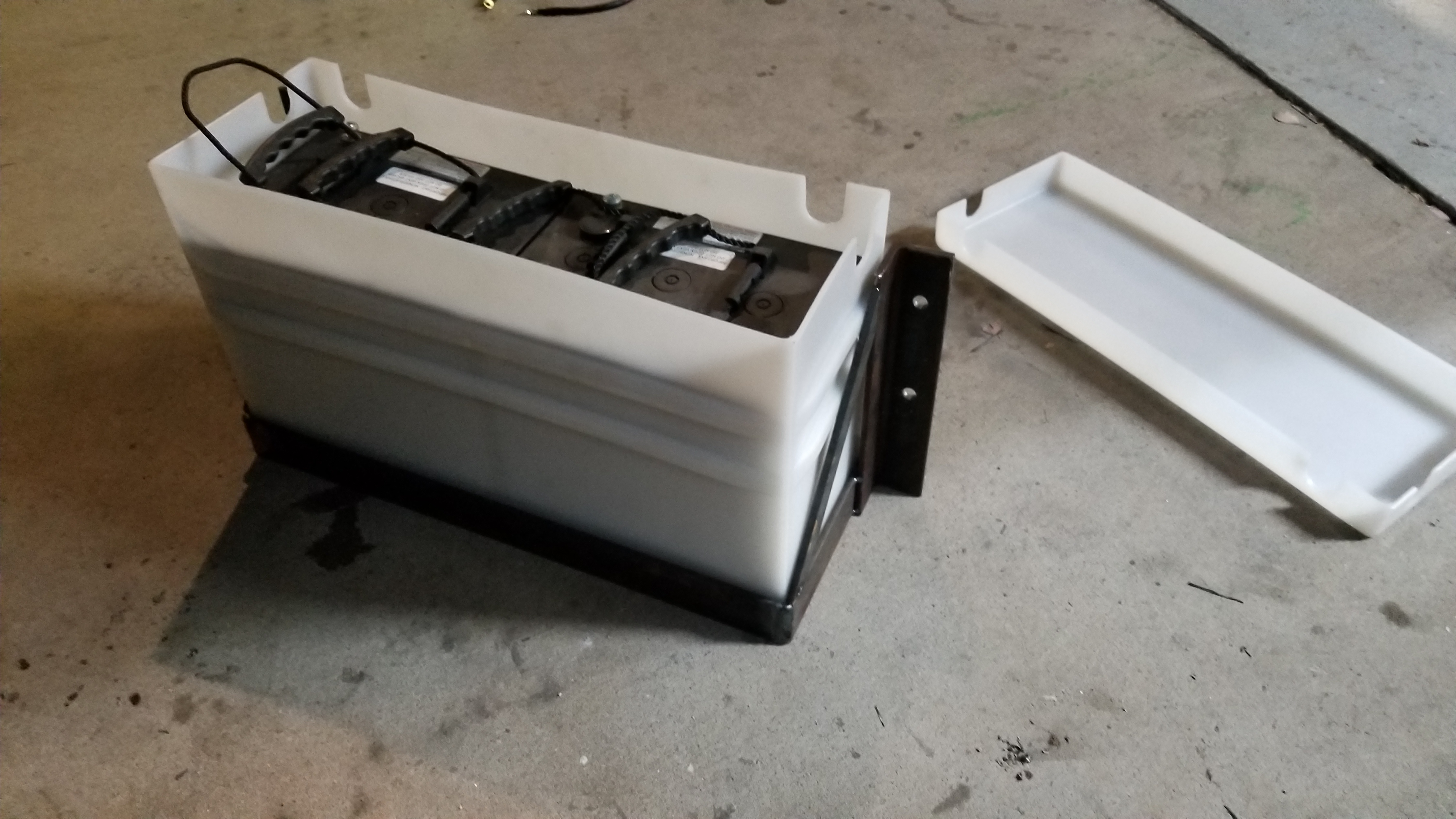
To be conservative I wanted to oversize my batteries a bit so I multiplied by 4 for to get 144 Amp Hours (I realized to get this I’d have to have 2 batteries so to go overkill I got 2 batteries with 225 Amp Hour Capacity). This conservative approach would account for other unforeseen power uses like a friend showing up with a hairdryer wanting to borrow my inverter outlet. Or at a dirtbag party, having 12 climbers wanting to all plug their phones in at once! Plus you have to remember that batteries aren’t 100% efficient and as they drain they will have a harder time delivering the current your appliances require.

The battery’s capacity will change the dimensions of the battery body (taller, longer, ect.) so keep that in mind when choosing your battery because you will have to find a place to store it!

Inverters: So you want to use that hair dryer from your house in your van eh? Your batteries deliver 12 Volts DC (direct current) and if you look at your hair dryer plug, it requires 125V AC (alternating current) at 15 Amps (full power). AC and DC are not equal! You must have an inverter to accomplish this. I won’t get into the nuts and bolts of how it works (there are two large coils inside the box which use induction and magnets to transfer the power from DC to AC) but all you really need to understand is that the Power IN ~ Power OUT.
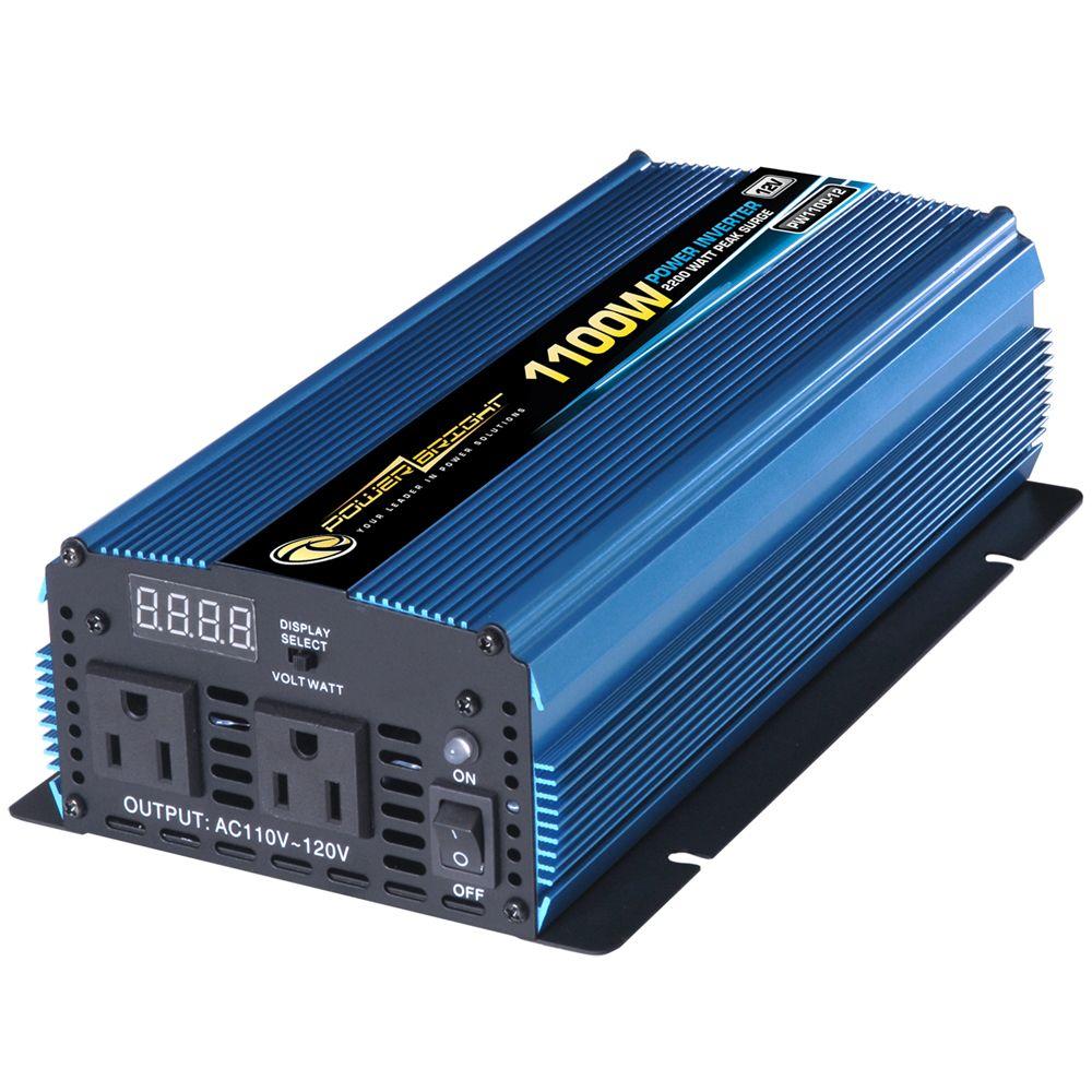
Image result for Inverter

So you already have power from Eq2 I gave you earlier. No matter if it’s AC or DC, power equation is the same (with a little loss for efficiency of course). Your inverter is taking input DC power from your batteries and outputting AC power to your hair dryer.

Eq3: Pin = Pout, and Eq 2: P = IV

V(AC) * I = V(DC) * I      

Example: Hair Dryer

(125 Volts AC)*(15Amps) = (12 Volts DC)*(DC Current)

Solve for DC required current = DC Current = (125V*15amp)/(12V) = 156 amps.

So it will require 156 DC amps to run your hair dryer. Use this example to calculate how many amp hours you will need for drying your hair for ½ hour. That will be 75 Amp Hours. Throw that into your battery sizing calculation.

Let’s see if you understand everything we have covered with the next example. Let’s pretend you have a fully charged 12V system with batteries that can output 200 Amp-Hours of current. You have your inverter wired up, you aren’t charging your batteries, and no other electronics are turned on. You start to dry your hair at full blast and then something distracts you, you get out of the van to check out whatever wild animal is lurking around and forget all about the hair dryer. How long will your hair dryer run before your batteries (buckets) run out of juice?

Hair dryer uses 156 DC amps. Time = (Amp Hour battery rating)/ Current used  = 200AH/156 = 1.28 hours. So if you aren’t back in around 1 hour and 15 minutes, your batteries will be totally dead and you’ll have to charge them.
Image result for hair dryer in van

Sizing your inverter: Sum up the Wattage for all the plug-in AC appliances you plan on using AT THE SAME TIME. If you only plan on using one appliance at a time, just use the one Wattage rating and size from there.

Example: Hair dryer (125V @ 15amps = 1875 Watts). You will need at least a 2000 Watt inverter.

The surge capacity of your inverter is usually twice what the inverter is rated at. So a 2000 Watt inverter will have 4000 surge capacity (which means how much power before the thing starts melting). If you plan on running both a hair dryer and an induction stove at the same time, just add them up and pick something rated a little bigger Wattage.

Charging: Let’s move on to filling your buckets (charging your batteries). There are a few ways to charge your batteries: solar, van alternator, gas generator. I chose solar because I wanted to keep my charging system and batteries for my appliances totally separate from the van’s wiring system. Choose your poison.

Sizing your solar system: There are typically (depending on where you live, weather (clouds), time of year, ect) 12 hours of sunlight in a day. That means you can only collect power during that timeframe. The Power (Watts) will be collected in the solar panels and converted to 12 Volts with a charge controller which will in turn fill your batteries. The charge controller does a ton of work for you, it converts the voltage and current from the panels for you, it stops charging the batteries when full, and alerts you when your batteries are almost empty. Your panels will run at different voltage and currents depending on how you wire them up, I will let Renogy take over that discussion.

Image result for solar panels renogy

The solar panels are generally rated in Watts. This is the power that they can collect over the surface area of their face. Remember from equation 2 (Eq2) that Power = I*V and equation 3 (Eq3) Pin = Pout. Lets calculate the current you could acquire over a 12 hour (daytime) period with a single 100 Watt panel.

Pin (from solar panels) = Pout (Charging your DC system) = V (DC volts) * I (current)

I (current) = Pin / V(DC) = 100 Watts /12 Volts = 8.33 Amps.

So over 12 hours you can accumulate: 8.33 Amps * 12 Hours = 100 Amp Hours of juice

You can see the problem here that if you have a 200 Amp Hour Battery system, in perfect full light for 12 hours that you would only full it half way (by collecting only 100 Amp Hours of electrical capacity). Thus you can install a second 100W Solar Panel. So now you have 200 Watts inputting from solar, and you’ll get twice the current to charge your batteries (in a perfect world when the sun is always shining and you aren’t running appliances during the day, ect ect).

With this information you should be able to size your solar system and choose your battery size as well as your appliances.


Click for Basic Circuits Details

Basic Circuits:

You have a power source (battery) and wire connecting an appliance (fridge) which requires a certain current to function.

If you throw a switch into this system you can turn the component on/off by breaking/completing the circuit.

Now to protect your components in this system you will need a fuse (resistor) that will burn up above a specified current. If for some reason your fridge which requires 2.7 amps max suddenly receives 20 amps, it would fry the components inside. If you have a 10 cent fuse installed that can only handle 5 amps, the fuse would bust, thus protecting your 600$ fridge from harm.

This is the very basic circuit theory you will use for just about everything in your system. Power source, switch, component, fuse.

Image result for basic circuit w fuse

Fuse sizing: Each appliance should specify the size of fuse you should put in line to protect the component. You can find this information in the components manual. If it does not specify the fuse required, then use the following rule of thumb.

Fuse =(Max appliance current * 1.5) round up.

Inverter Fuse = (inverter surge power/10)*1.2

Wire sizing: Each appliance should have a manual that specifies the size of the wire required. If there is no callout, use an online wire gage calculator to select the correct size of wire (https://www.wirebarn.com/Wire-Calculator-_ep_41.html). I ran 18 AWG wire from the majority (but not all) of my components.

I also used a wire loom to run as many wires as possible for organization.

Image result for wire sizing chart


Putting the Electrical Theory to Work: Wiring up your van.

Now that you have the appliance, wire size, fuse size, and a basic understanding of simple circuits, let’s start putting theory to work! If you followed the wire running Step 3 then all of your wires should be located in one central place you have allocated for the fuse box area (this includes all your wires for appliances and the two extension cable plug-ends meant for the inverter.

Your fuse box will be power central. I decided to mount my batteries below the body of the van onto the frame itself. This will save me a ton of room inside the van for storage. I placed the batteries as close to my fuse box area as possible. Once this was complete you can start mounting your components to the side of the cabinet and start wiring things together.

Tools/Materials used:
Procedure
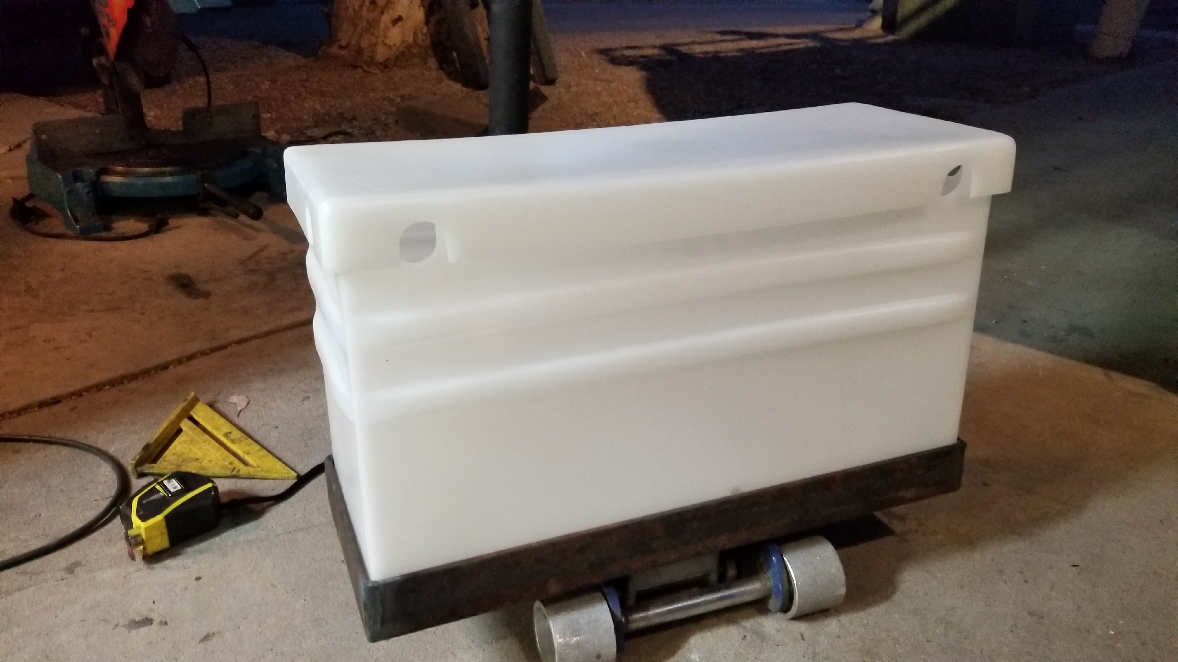
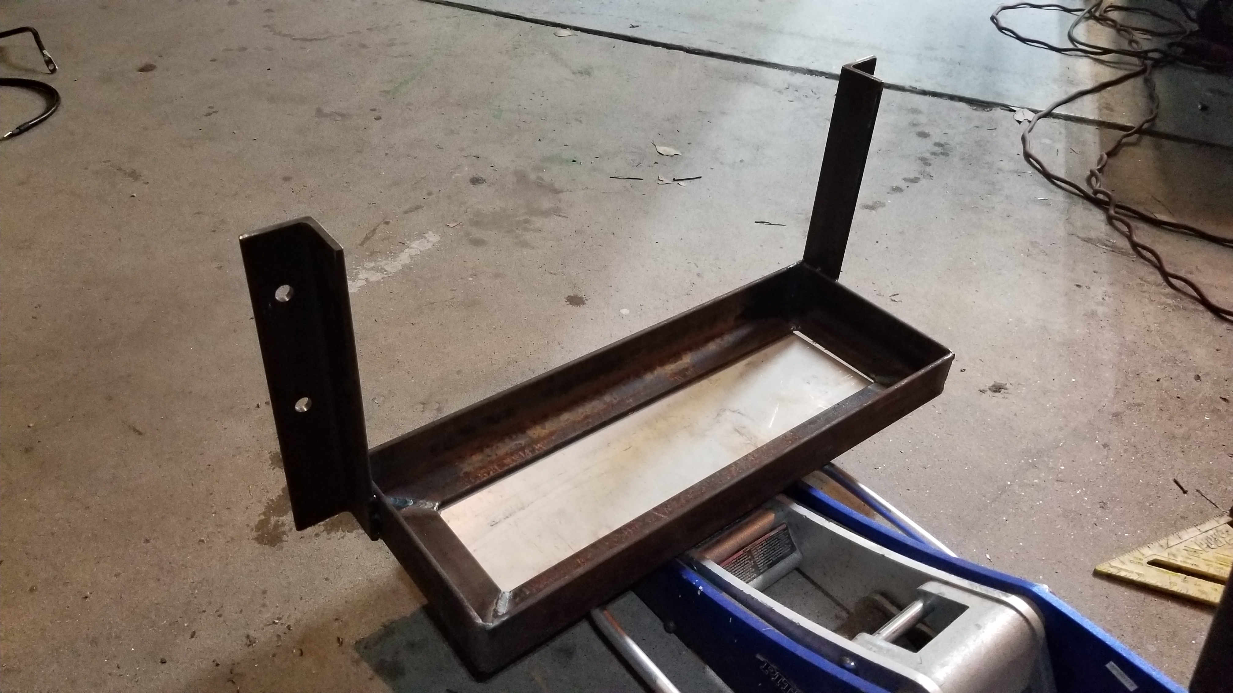
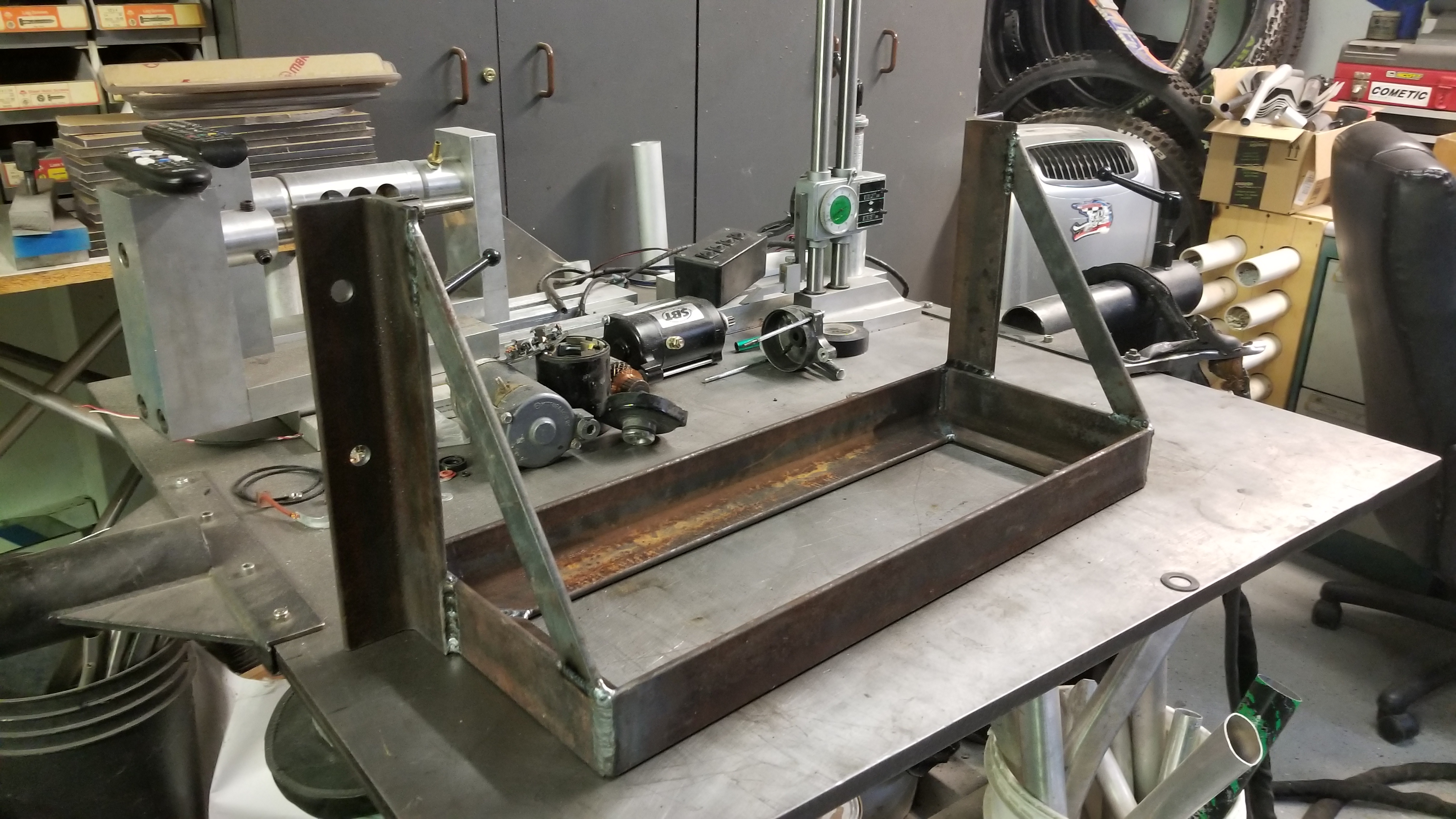
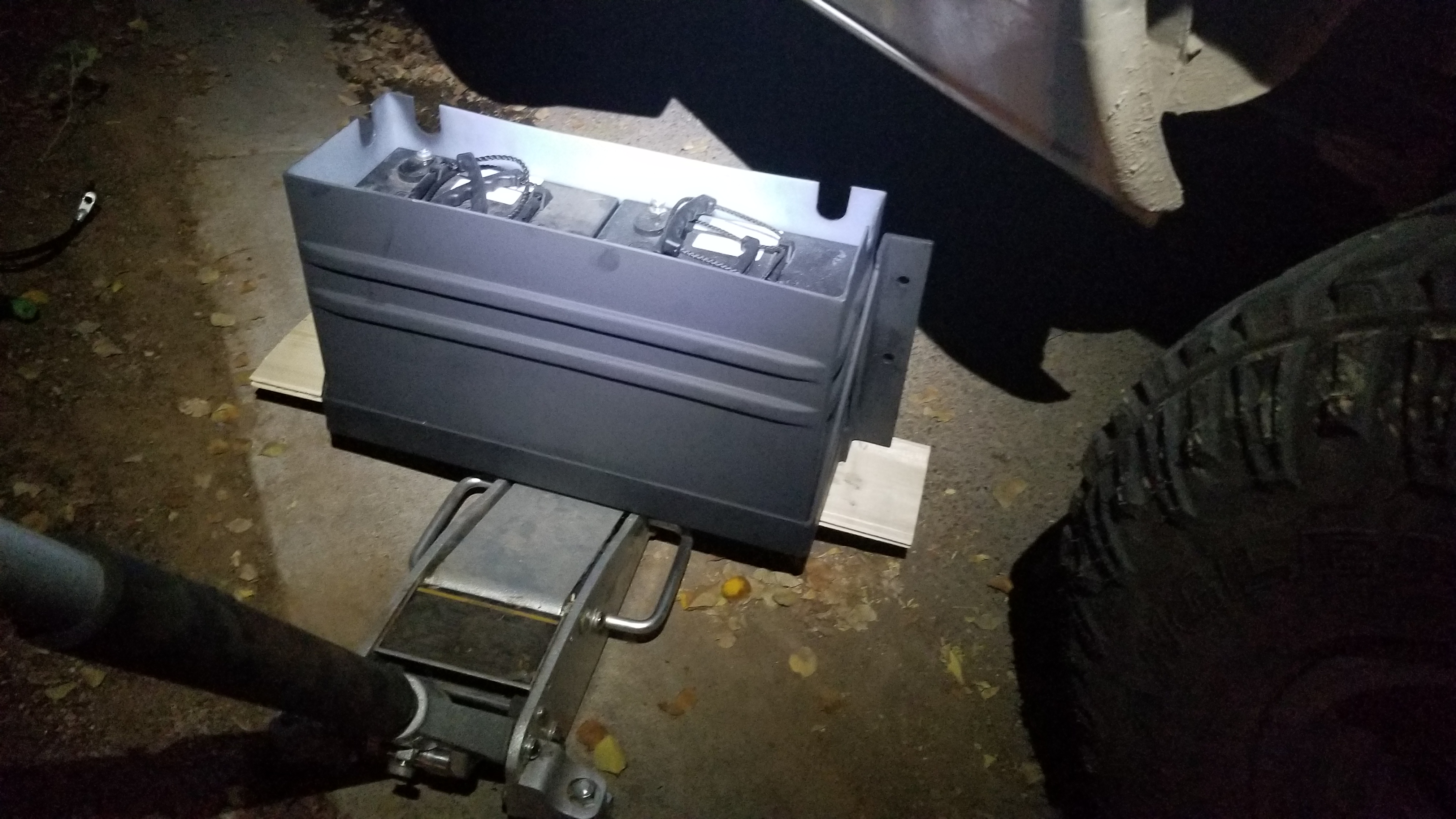
  • Build a battery box to house your deep cycle batteries (thanks Adam!).
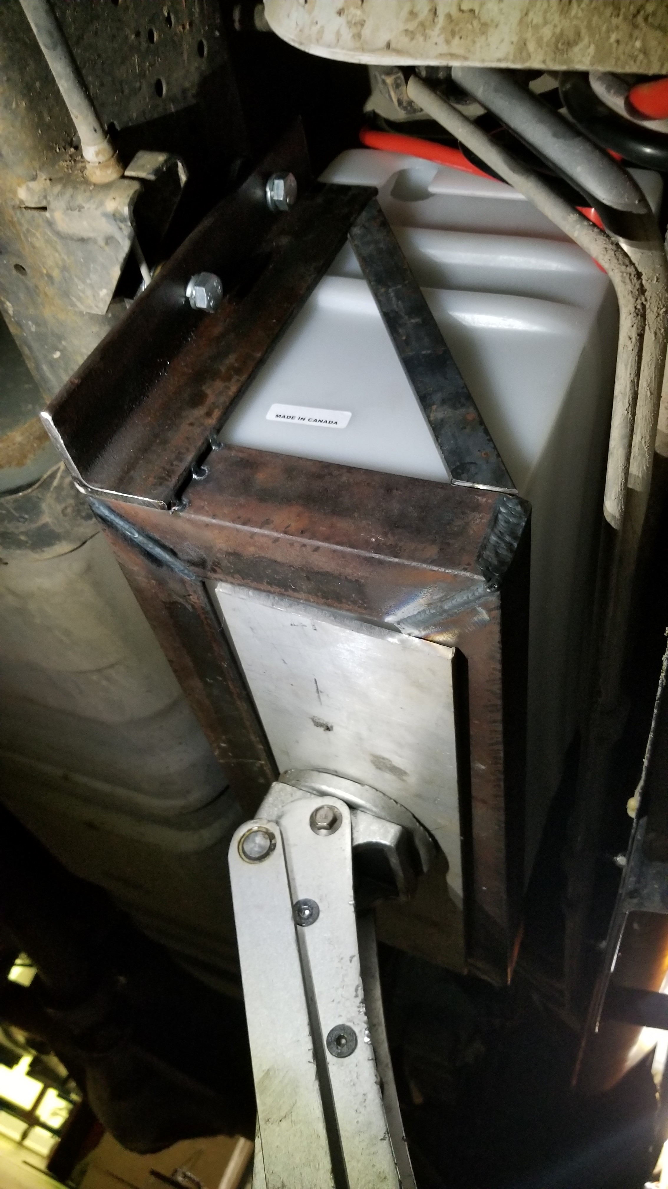
    1. Grab your plastic battery holder for dimensions and start cutting angle iron to make a frame around it.
    2. Drill 4 holes that will be used to mount the metal battery frame to the van’s frame.
    3. Weld the frame together and make sure your plastic battery holder fits snug inside without being pinched.
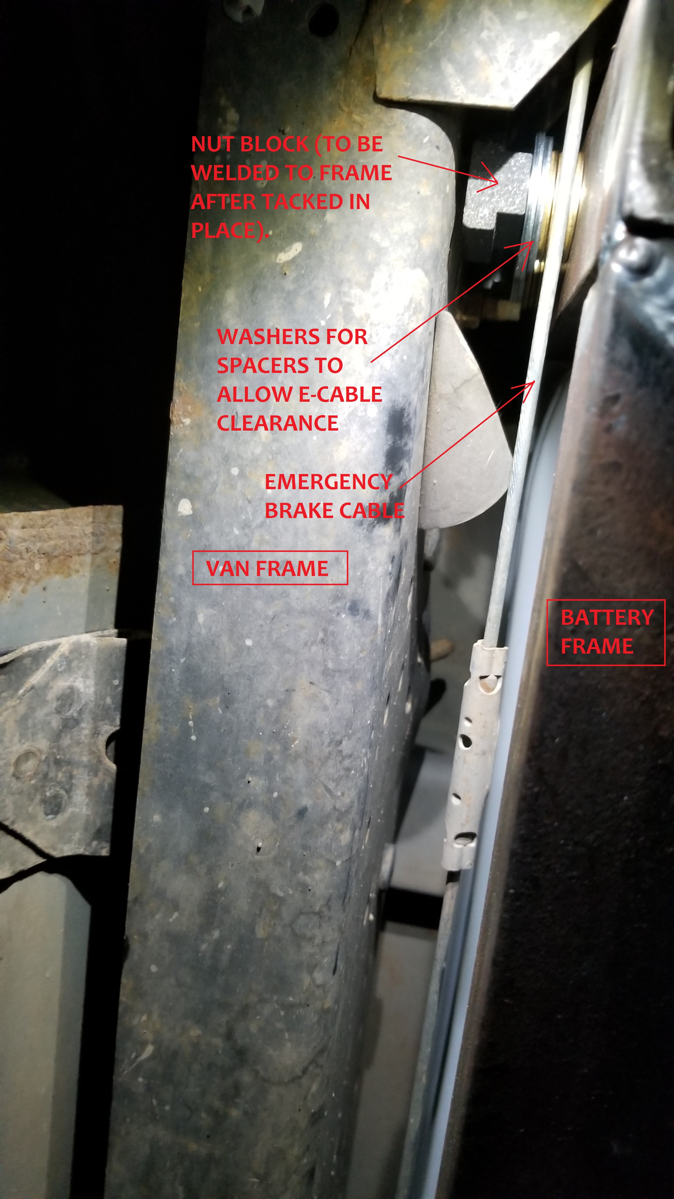
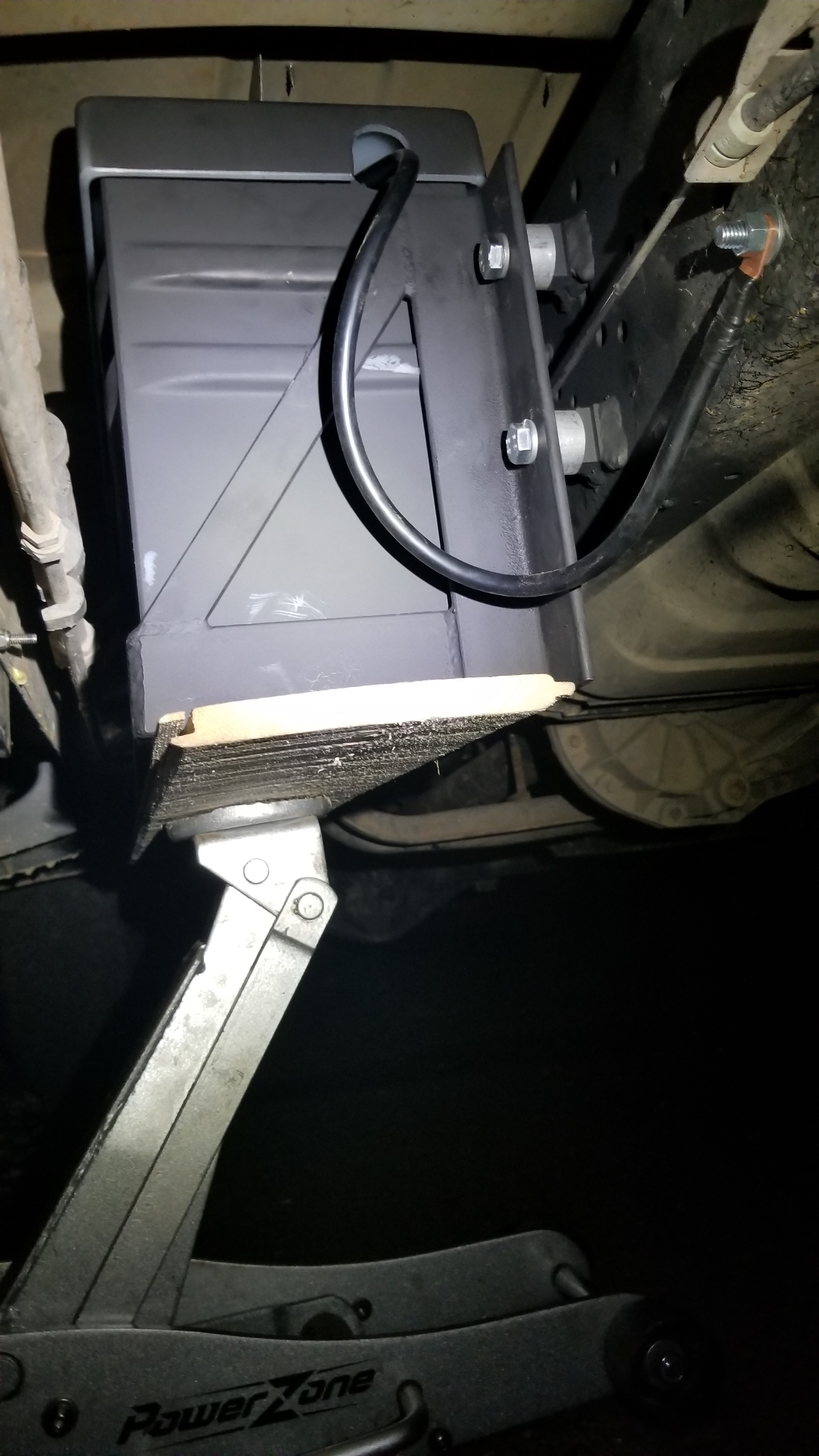
    4. Lift the battery frame up next to your van’s frame with the bolts and nut plates screwed onto the end.
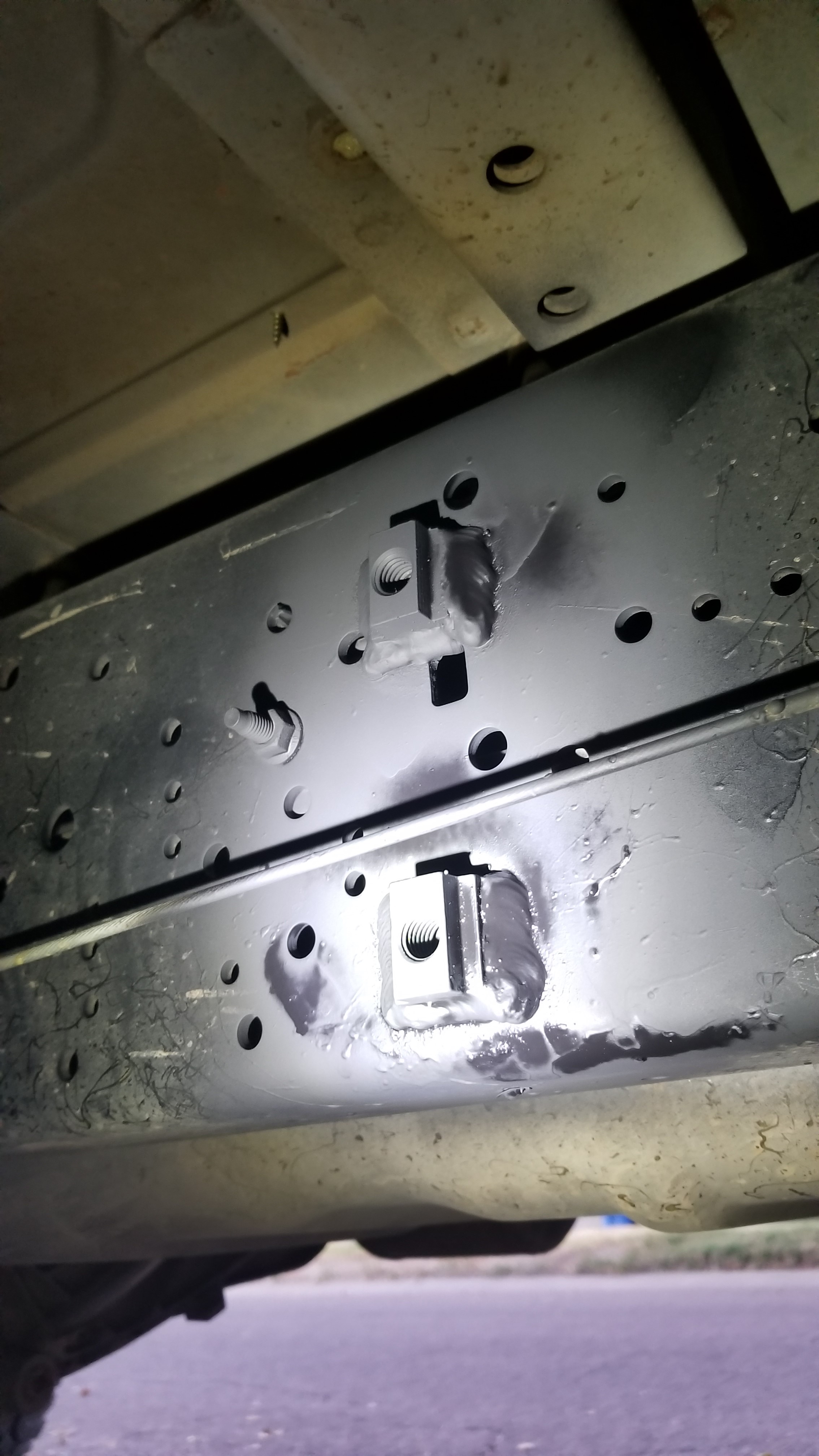
    5. Tack weld the nut plates to the frame, remove the bolts, lower the battery frame down, fully weld the nut plates to the frame. Video: https://youtu.be/UR8SUxsoaoc

      Bottom view, getting ready to tack the nut plates into place.

      Nut plates welded on and sprayed with anti-rust spray paint.
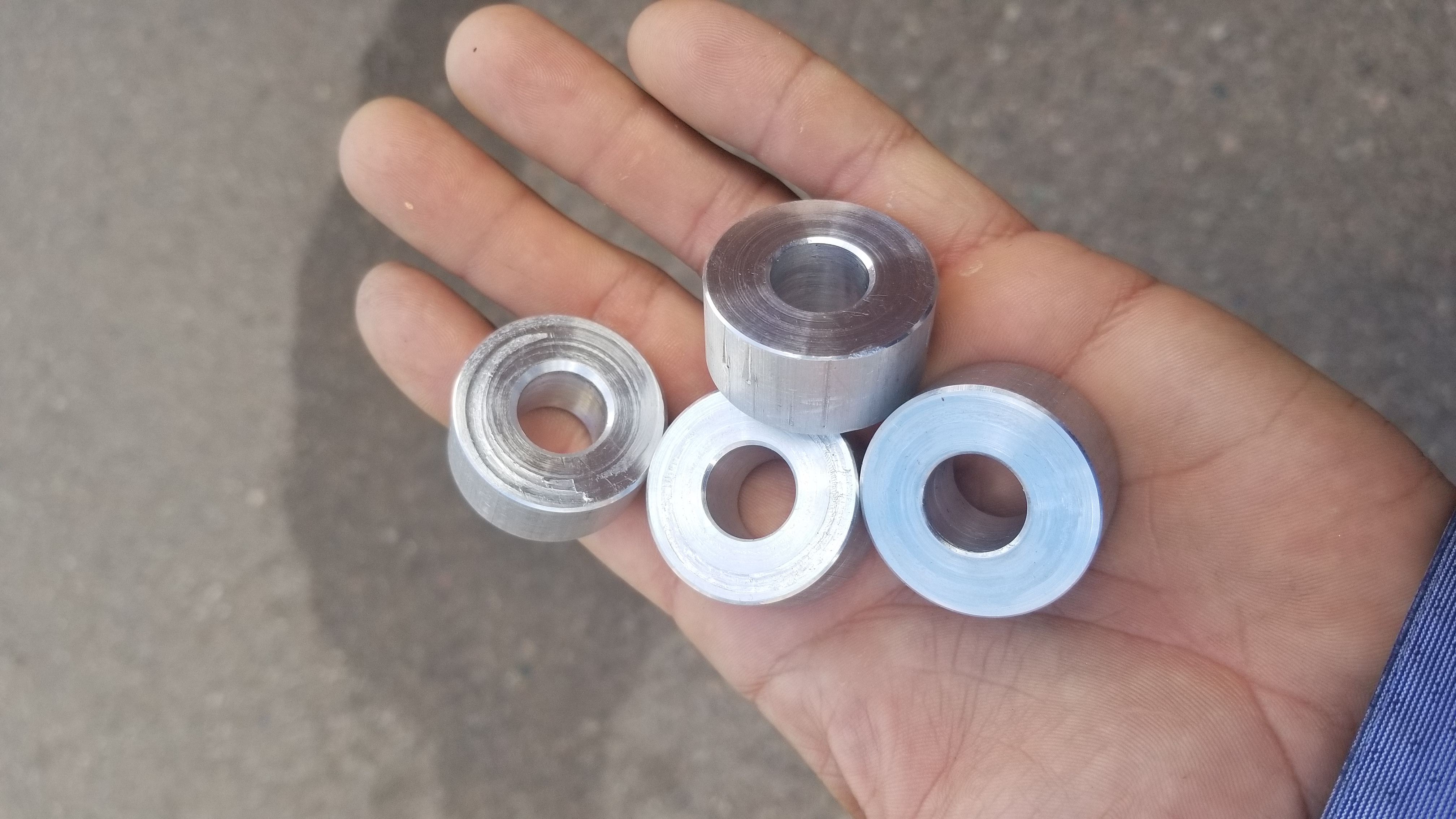
    6. Make four spacers to go behind the frame so it will clear the emergency cable that runs next to the frame.
    7. Spray paint the Nut Plates, Plastic Battery Box, and Battery Frame with anti-rust spray paint.

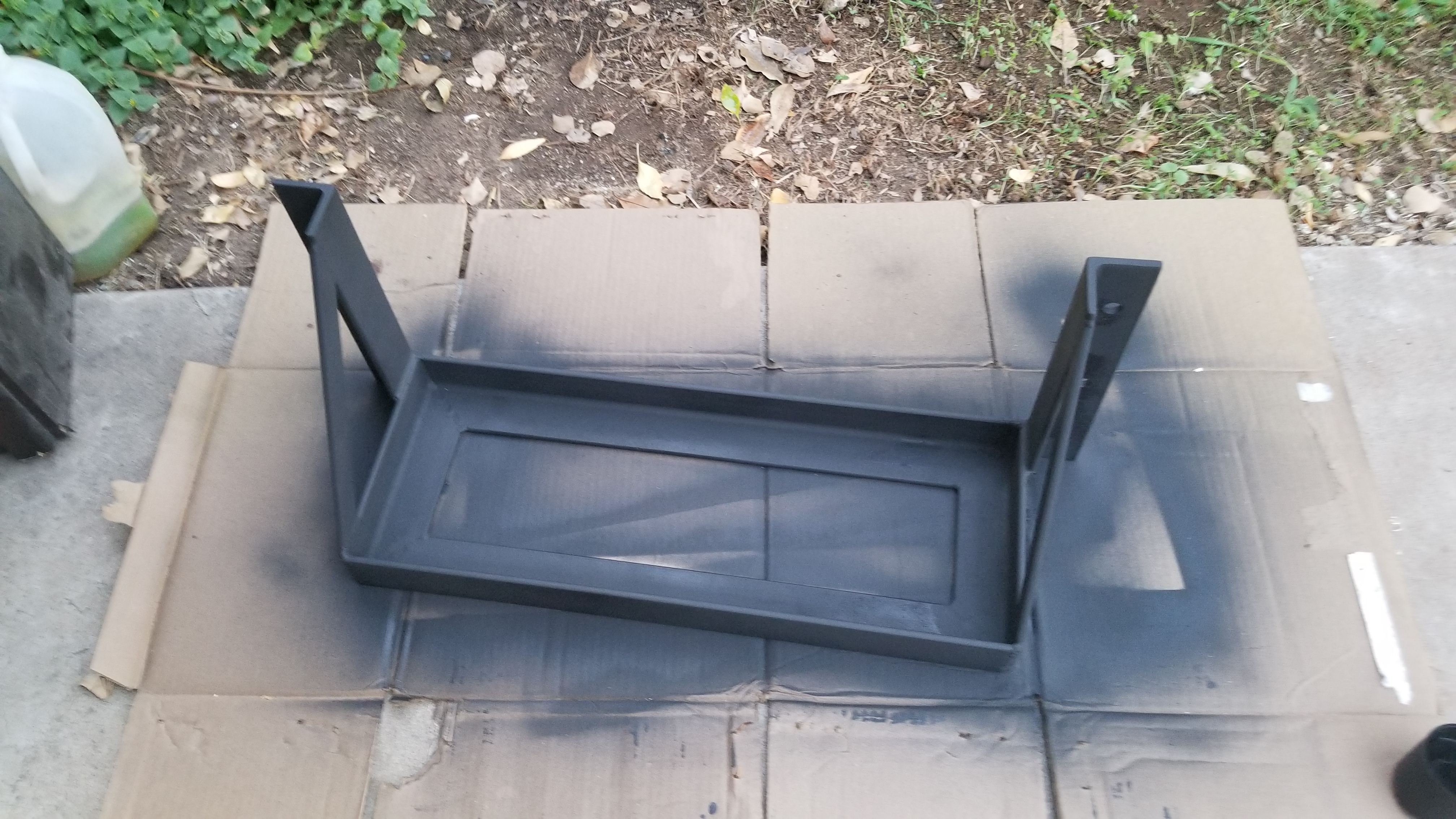
      Battery Frame, all painted up!

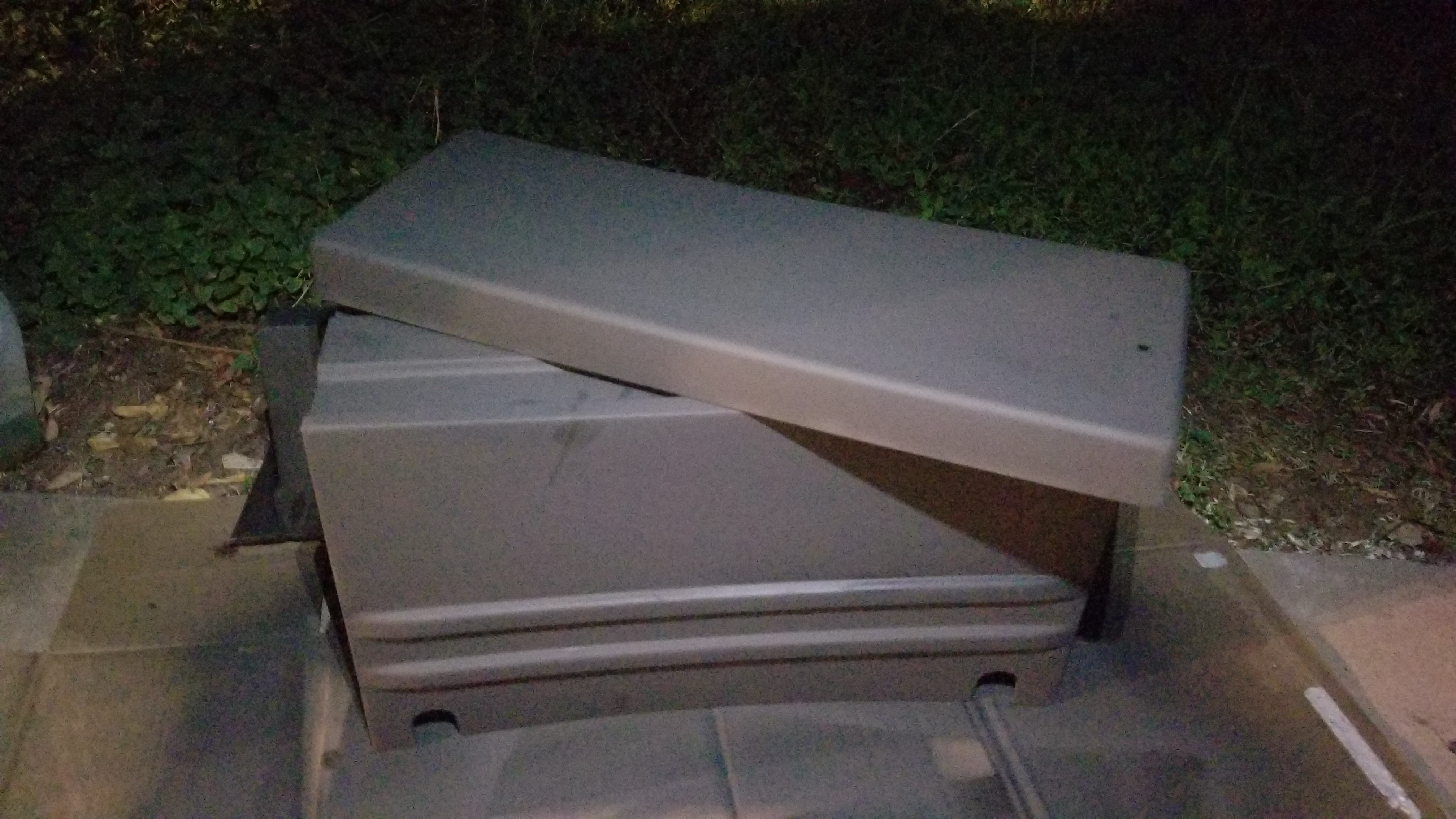
      Battery box, painted, ready to roll!
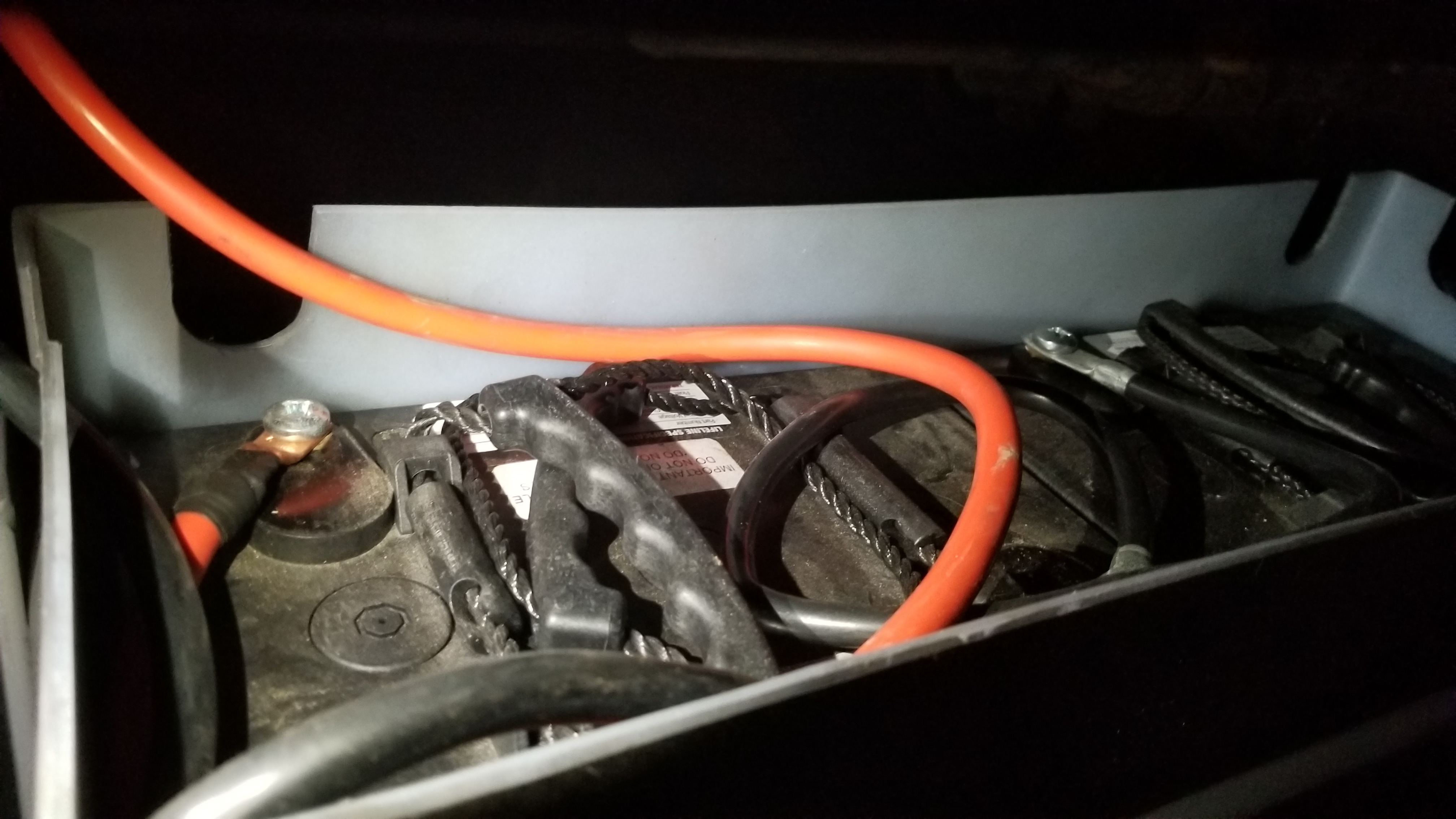
    8. Install the batteries into the box, wire them in series (I have two 6V batteries, wire in parallel if you have 12V batteries), put the lid on, lift it into place and bolt the battery frame to the van’s frame.

      Batteries in, ready to be wired up!

      I wired my batteries in Series as they are two 6V and I want a 12V system.

      1. Important! Make sure to have hot (red – positive) and ground (black – negative) wires that are long enough to reach the frame (ground) and the fuse box inside your van while the battery frame is lowered to the ground (makes for easy maintenance and removal)
    9. Attach the ground wire from your battery to the van’s frame.

      Battery Box in place, bolted up, and ground wire bolted to Van’s frame.
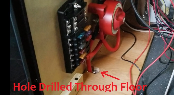
  • Drill a hole through the floor of your van just next to the fuse box area and the batteries mounted below the van on the frame. I found a precut hole with an oval stopper in it. I removed the stopper and drilled an identical hole through the wood floor of my van.
    1. Once the hole is drilled, insulate the edges of the hole with a rubber grommet to protect your battery wires.

      This picture only shows positive coming through the floor, a negative ground wire will soon follow
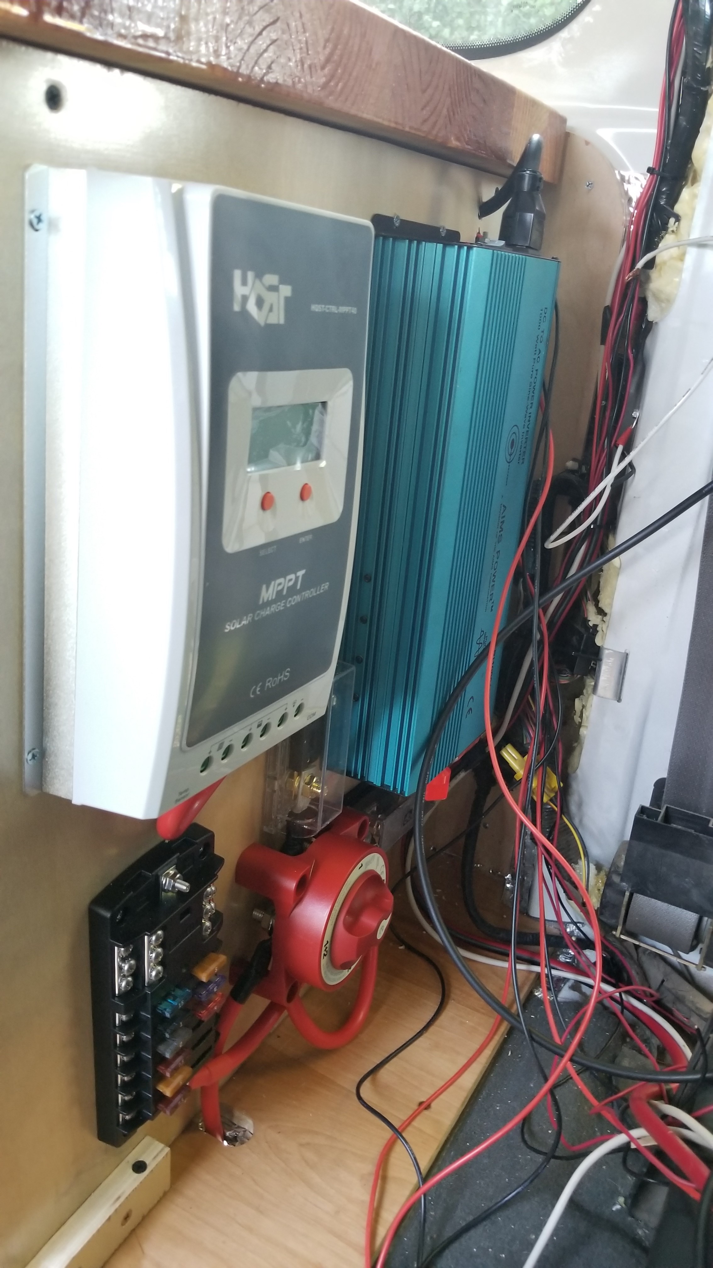
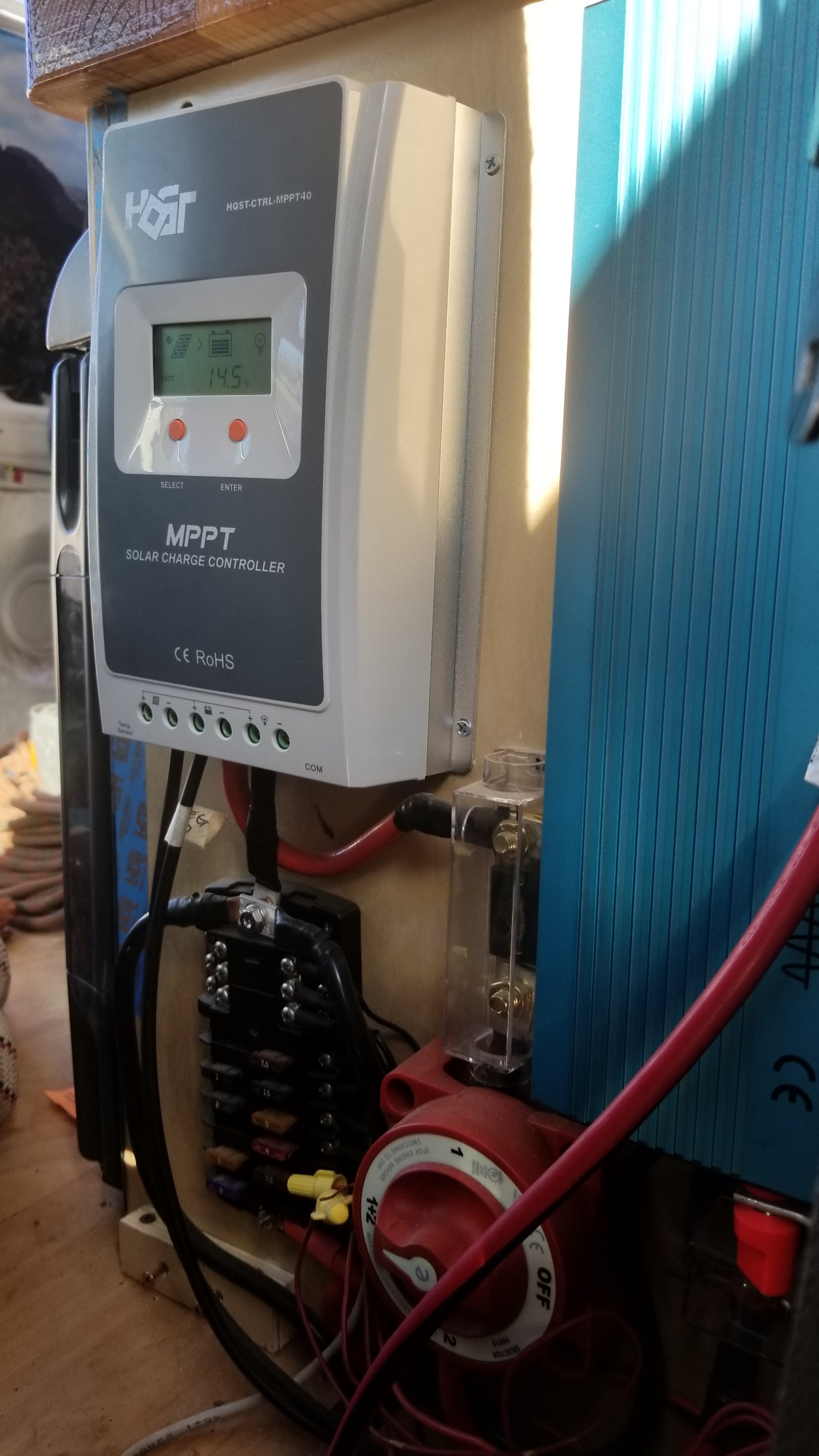
  • Mount your fuse box, BlueSea power switch, charge controller, inverter, and two single large fuse holders (one for the inverter, the second for the charge controller).
    1. You’ll want to strategically place these so you can run large gage wire between the power and ground terminals.
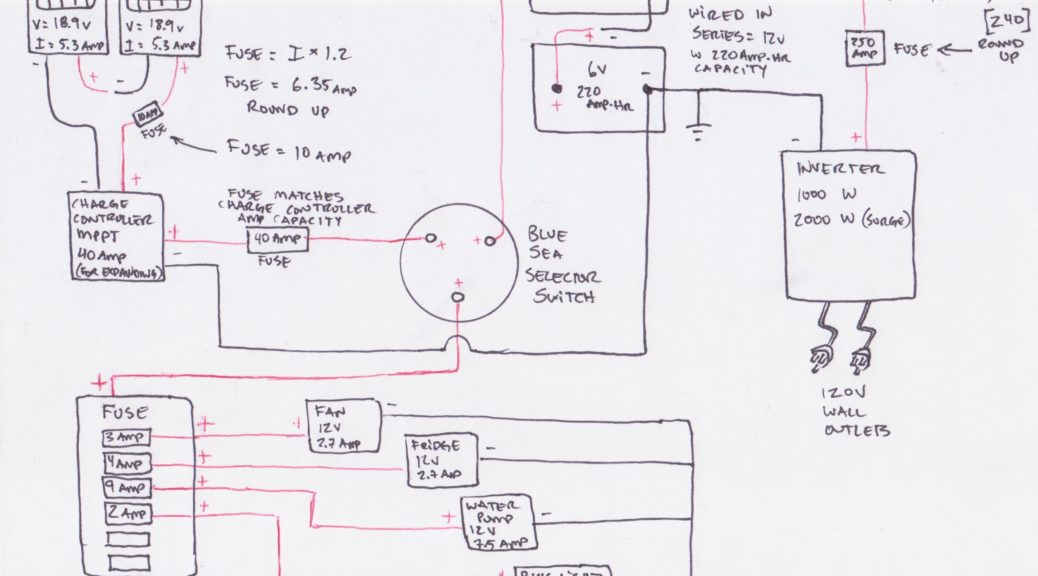
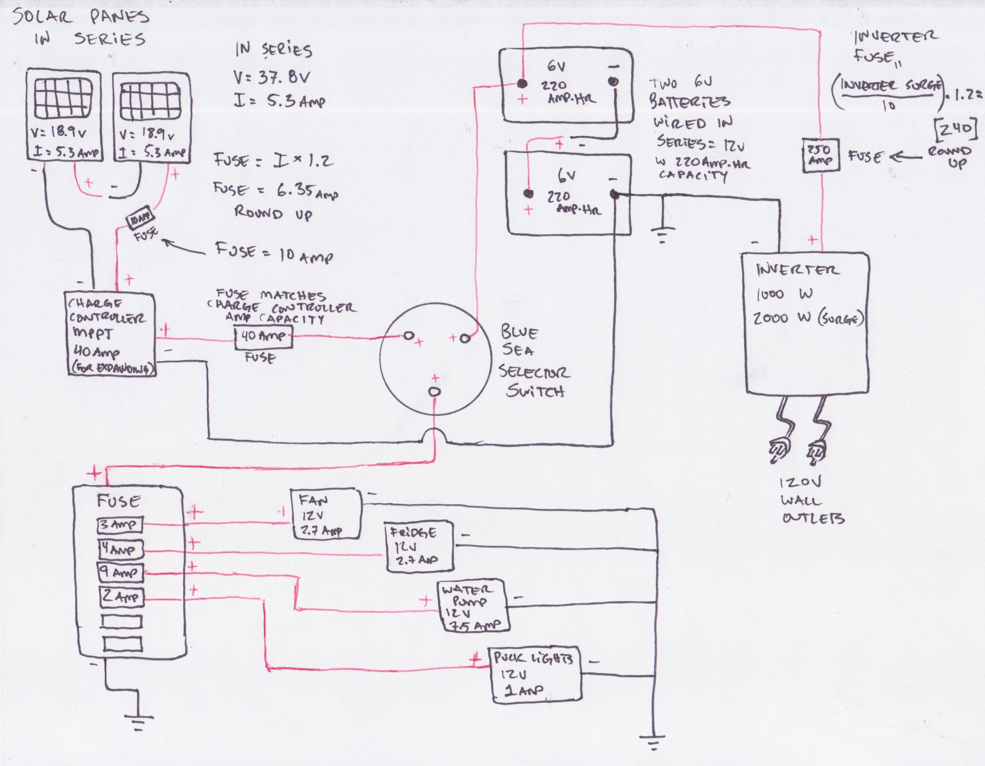
  • Once you’ve mounted these, start running your wires. I wired my system in a way that I could isolate the batteries from the fuse box and the charge controller if I so chose. I opted to run my fuse box straight to my batteries instead of to my charge controller. If I would have wired it to my charge controller I could have monitored the current used by all my appliances (perhaps I’ll do this in the future, but just wanted to keep it simple for now). I used the following wiring diagram I drew to wire up my system (this doesn’t show the switches I put in for the lights, and water pump – The fridge and fan have built in switches for on/off).
    Wiring Diagram for my Van (Click to enlarge)

    1. Run all your wires on the recommended gages to the fuse box. The recommended fuses and wire gages will be in each component manual.
    2. I utilized the wall switch I installed early on in the build for the ceiling puck lights, and will be used for the LED strip lights and eventually the cook area puck lights.
    3. Video: Shows generally whole wiring scheme – https://youtu.be/YqlrzXS5fnU
  • Now that you are ready, run the hot (red-positive) wire from your batteries to the Blue Sea switch. Double check everything, cross your fingers, and turn the switch on! Congrats! You either have power easily flowing to your appropriate appliances, or you have a crap ton of problems you have to run down and correct.
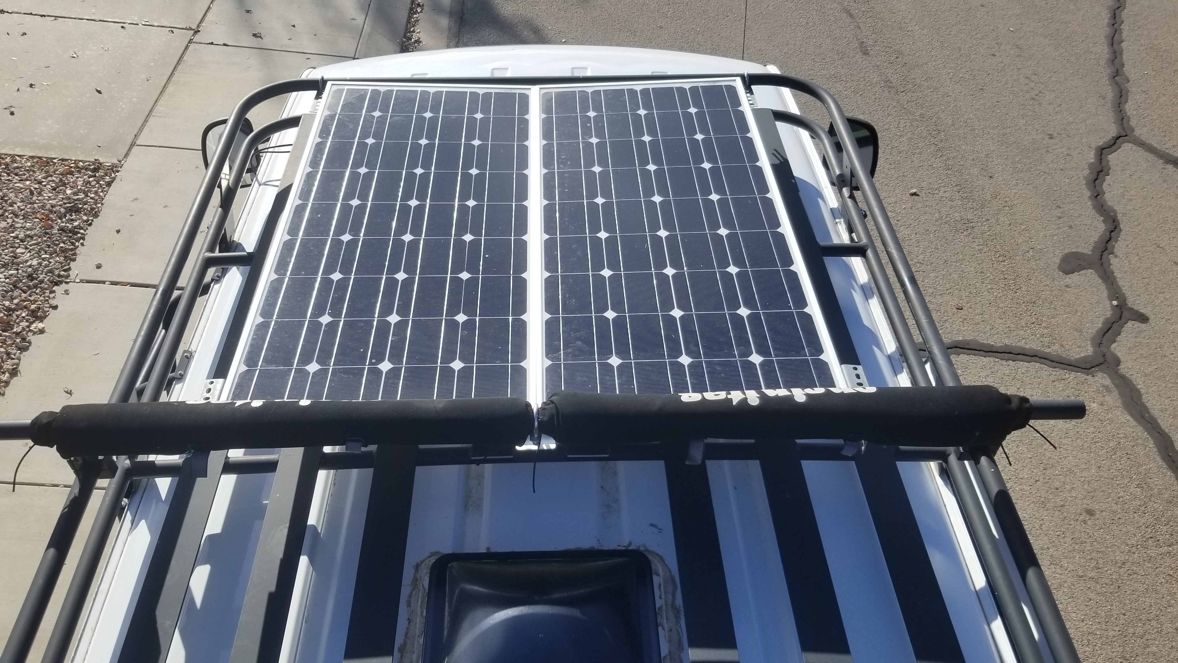
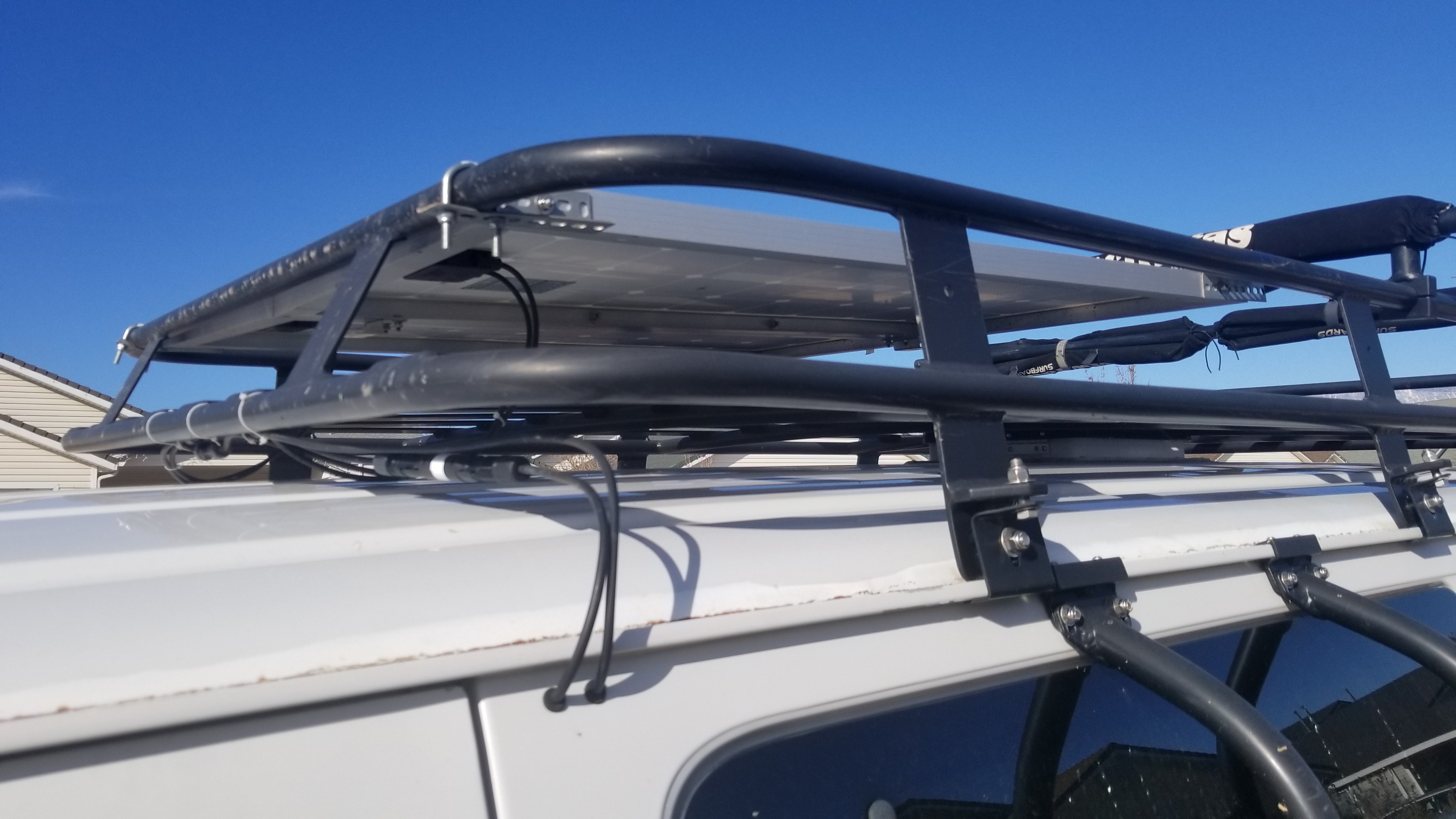
  • Install your solar panels on your roof. Tons of options here, I created some brackets that would keep the panels in line with my roof rack which cut down on air resistance.
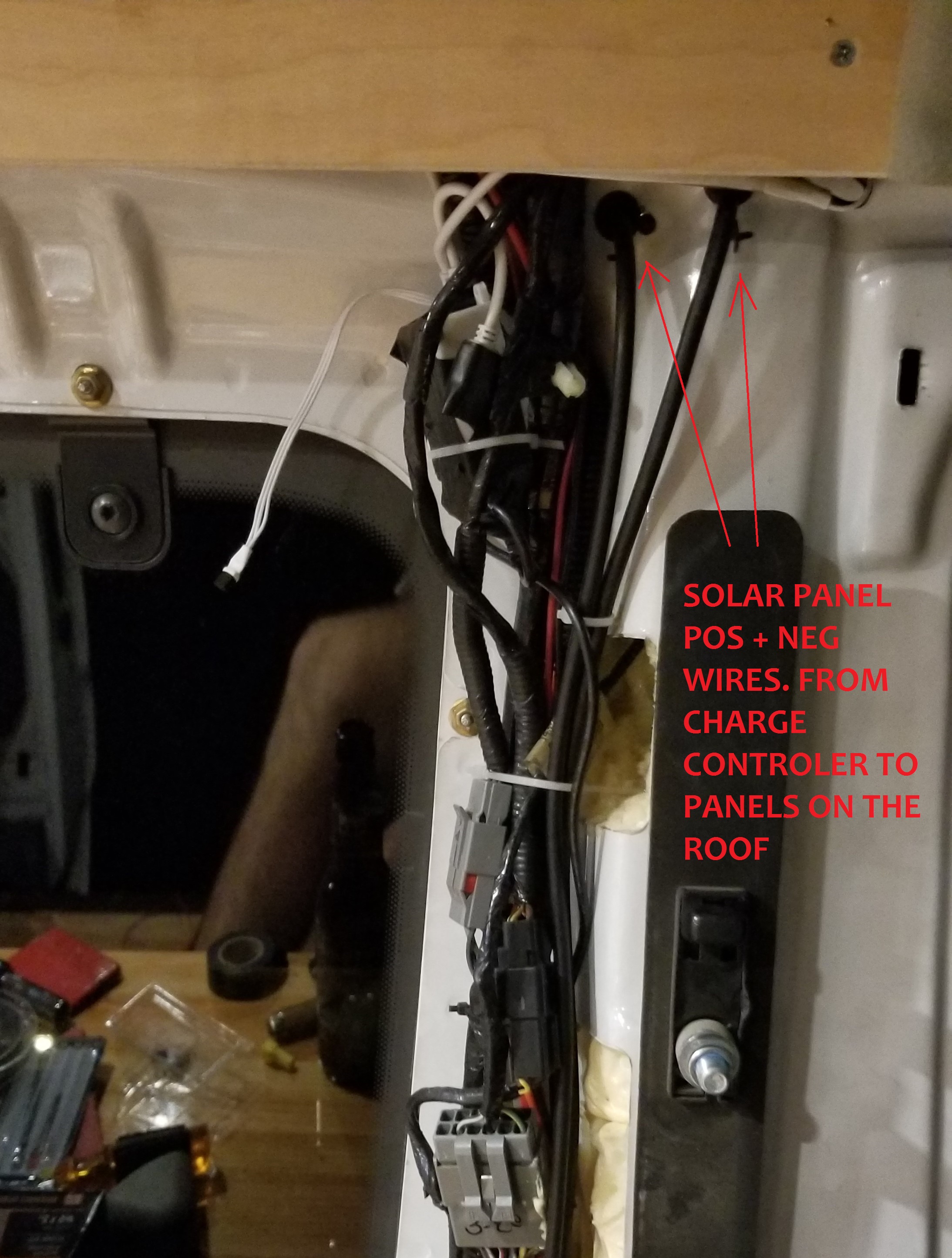
  • Drill two holes into the side of your van BELOW the rainguard lip where your roof meets the side body of your van. Run your wires through the body of the van and connect them to your charge controller.
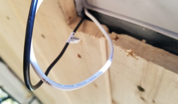
    1. Use rubber grommets to protect the wires from the sharp edges of the holes through your van body
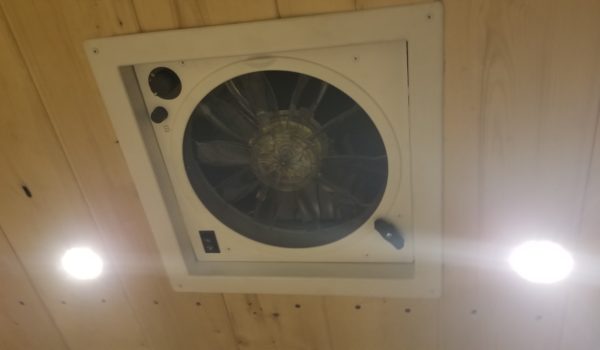
      Holes for panel wires from inside

      Wiring to panels, you can see my in line 10 amp fuse from renogy just below the roof rack
  • Now clean everything up, use ties and organize the mass bundles of wires to a tidy mess.
Share

CamperVan Build – Step 11: Finishing Touches

Share

Step 11: Finishing touches.

Whew, man it’s been a wild ride! The van looks good, but it isn’t the final version of what you envisioned. It about to be though! In this final push I closed most of the loose ends, and cleaned up all the ugly edges.

Tools/Materials used:
Procedure:
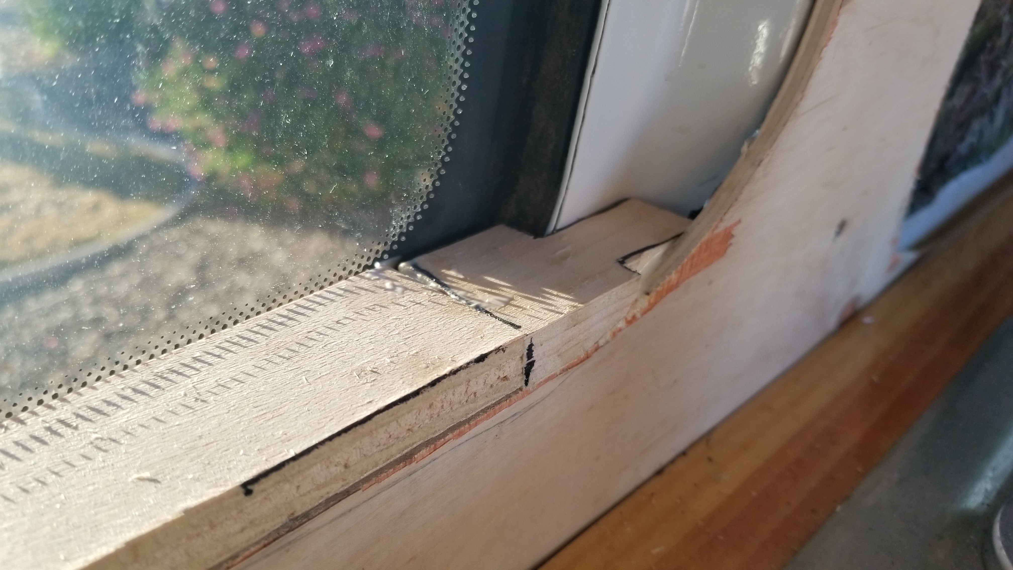
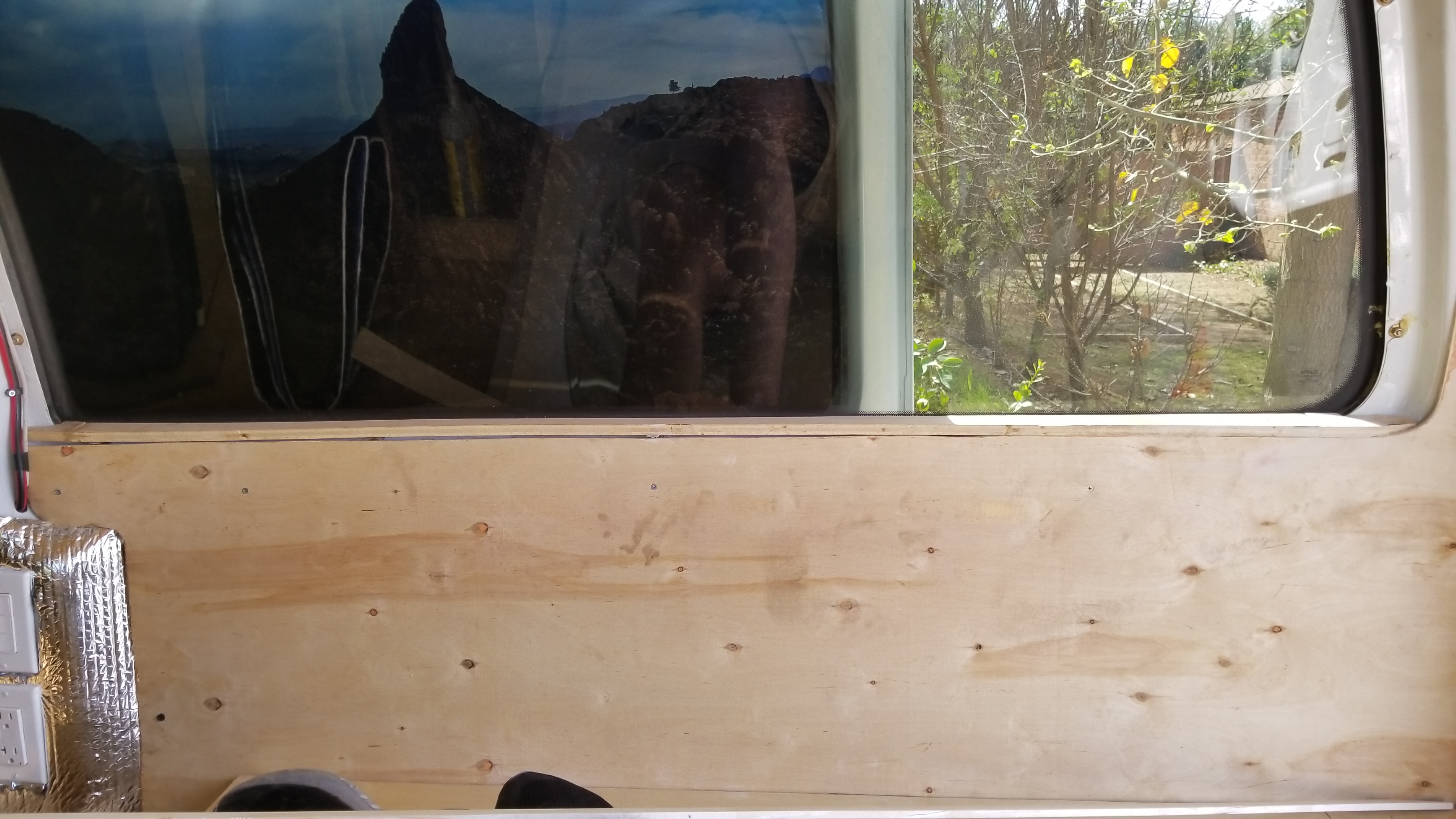
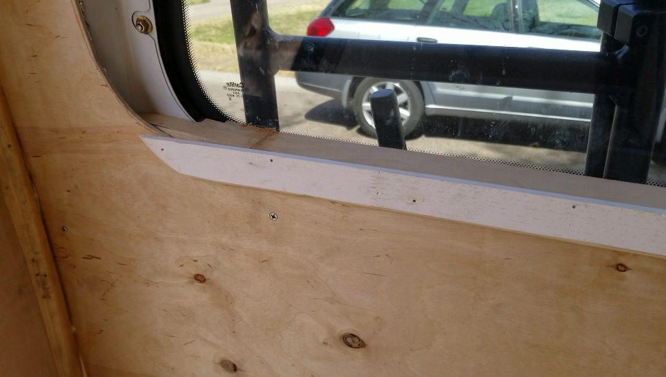
  1. Make window sills. I cut strips of wood to go between the glass and the wooden walls that I installed. This would create a windowsill, stopping anything from falling behind the walls from the windows. I used a finishing facing strip to clean the outer edge once installed. Sand it down to prep for paint!

    Window sill all installed, making custom pieces to seal off the edges.

    Install your window sill. I did this behind the wall with some L brackets, 3 window frame bolts, and 3 wood screws.

    Create a face board and install it with wood glue and finishing nails. This will clean up any imperfections at the seam.

  2. Complete the back corners of the van. The space where the back walls meet the side walls must be dealt with. I used some quarter round to accomplish this. Cut to length, cut slits in the back, and then soak in a water bath for a few hours to allow the wood to become bendable. Cover the back of the wood with wood glue and press the quarter round into the corners and nail it into place with finishing nails. Sand everything down to prep for paint.

    Unfinished corner, you can see the wall joint seam to the metal.

    Use the quarter round, soak it in water, cut slats in the back for bendability, then work from bottom up tacking it into place with wood glue and finishing nails.

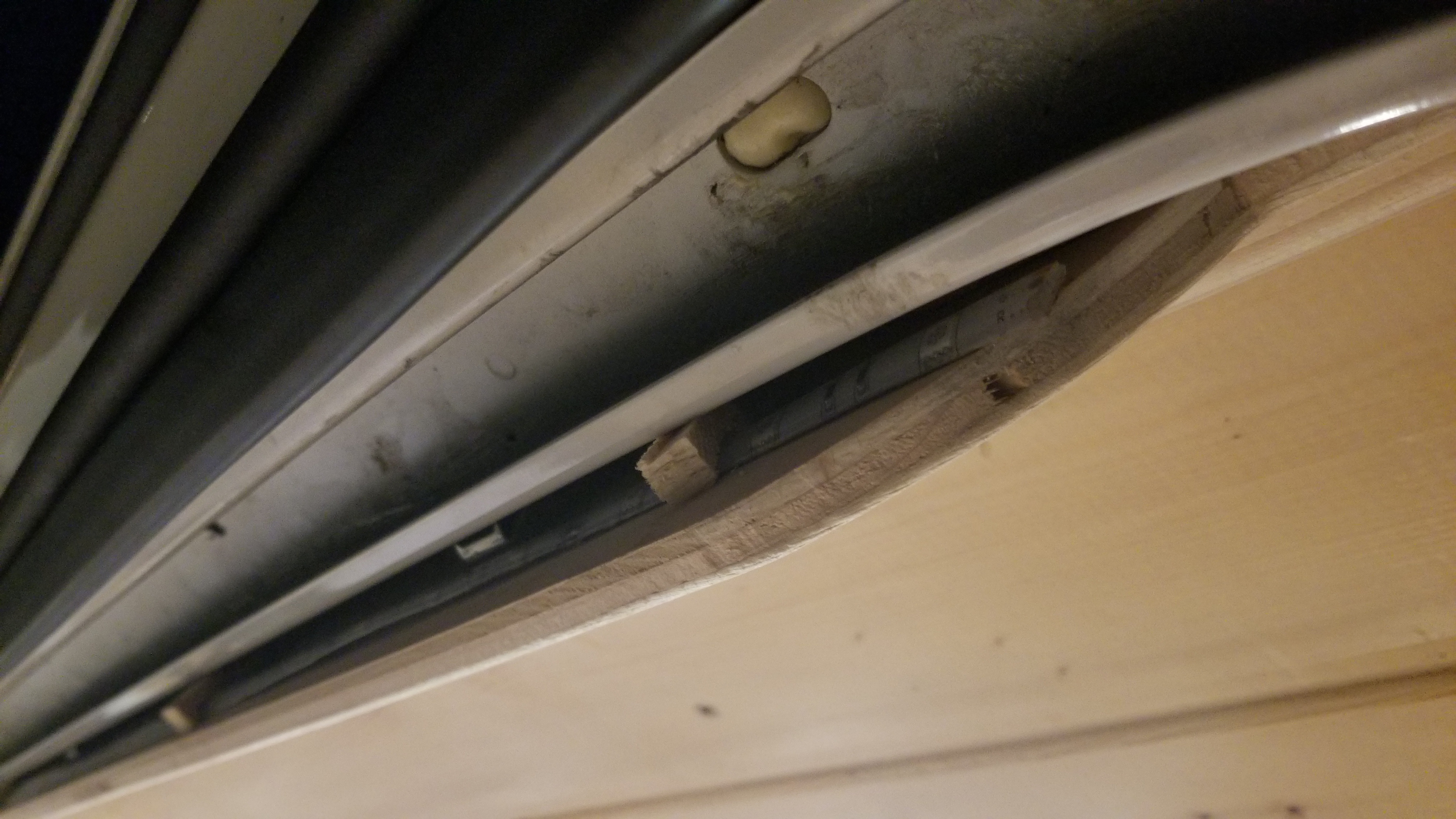
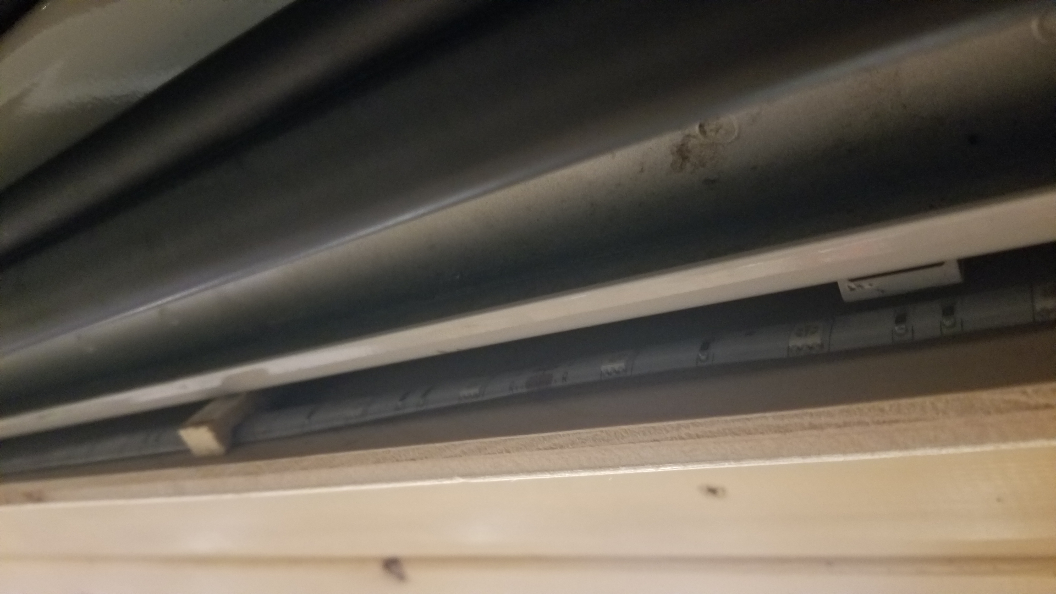
  3. Run the LED light strip behind the upper facer board. I held these in place with some wood ‘C’ clamps that I cut and glued over the light strip itself. The adhesive isn’t good enough on the back of the lights as it didn’t adhere to the wood so I had to create these ‘C’ clamps to hold them in place. Wire these lights into the light switch (that was run early on in the build).

    The glue on the back of the LEDs doesnt stick to wood well, so I had to make ‘C’ clamps out of wood and glue them around the light strips to hold them in pace.

    5 Color LED’s with remote!

    LED back lights installed and wired up!

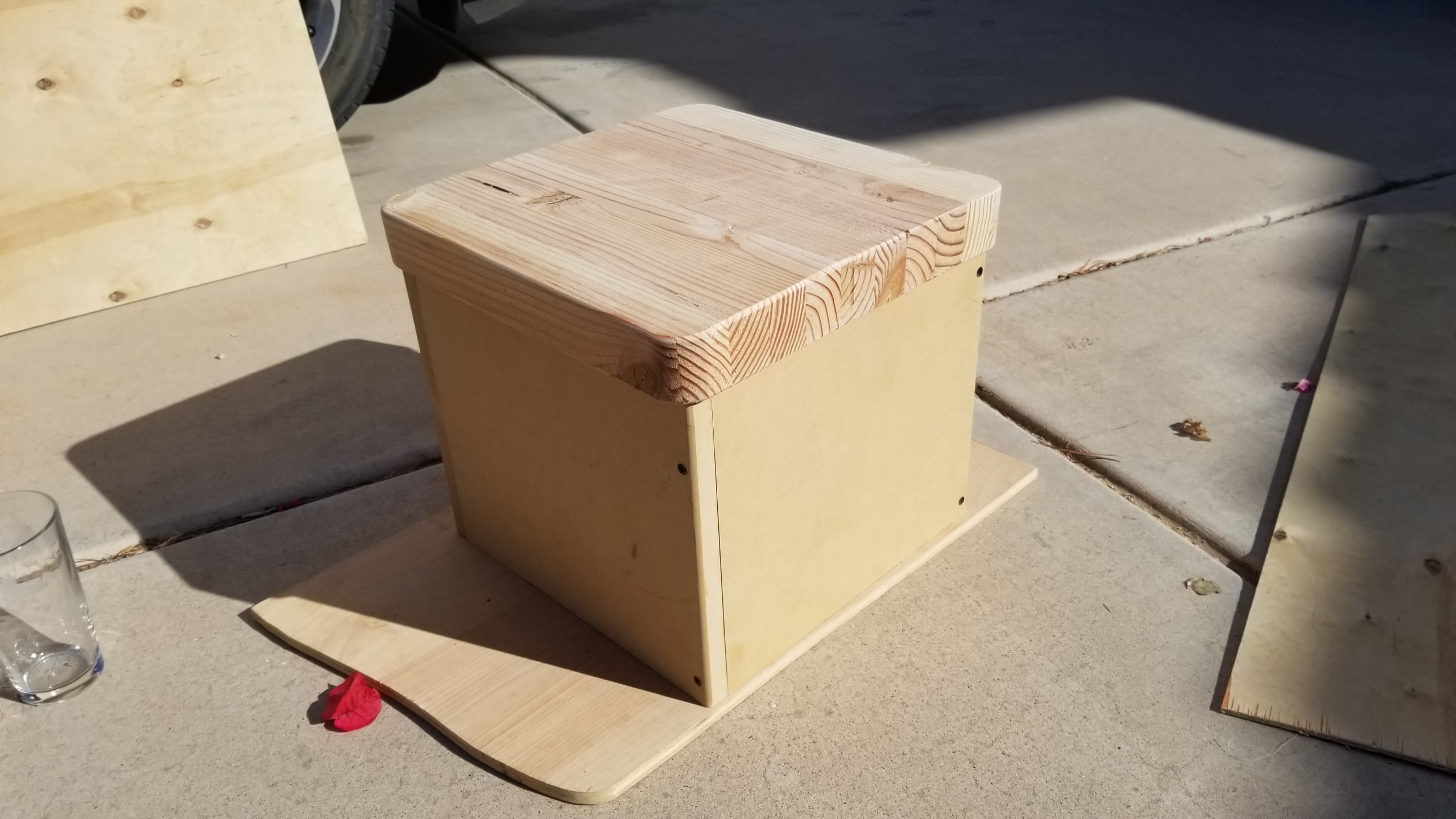
  4. Make the stool. My van does not have a pop-top or a hightop, therefore cooking must be done from a seated or kneeling position. I made a stool to accomplish this. I used one of the wooden cutouts from the counter top for the stove as my seat top attached with a small piano hinge, then stained and sealed it just as the counter was. The wood I used for the body was some leftover MDF my brother had laying around.

    Stool, all mocked up!

    Stained and working on the Glaze BarTop seal
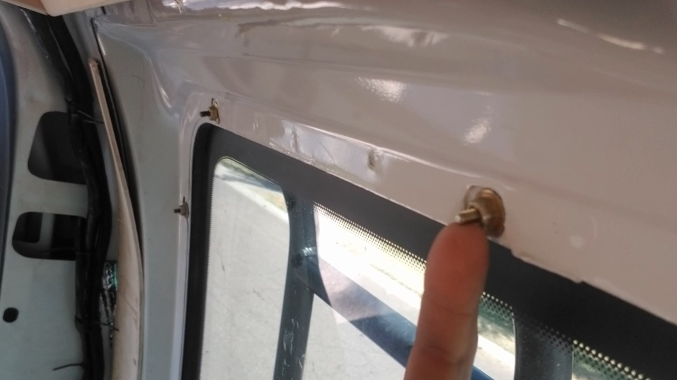
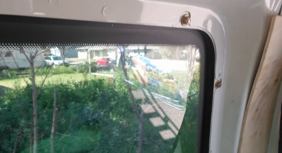
  5. Grind down any extruding metal. The bolts that hold the windows into place stick out quite a bit when not covered by the plastic interior plastic body that I removed during the stripping step. I used a metal grinder and cut these down.

    Window frame bolts sticking out. Before the grind

    After the grind
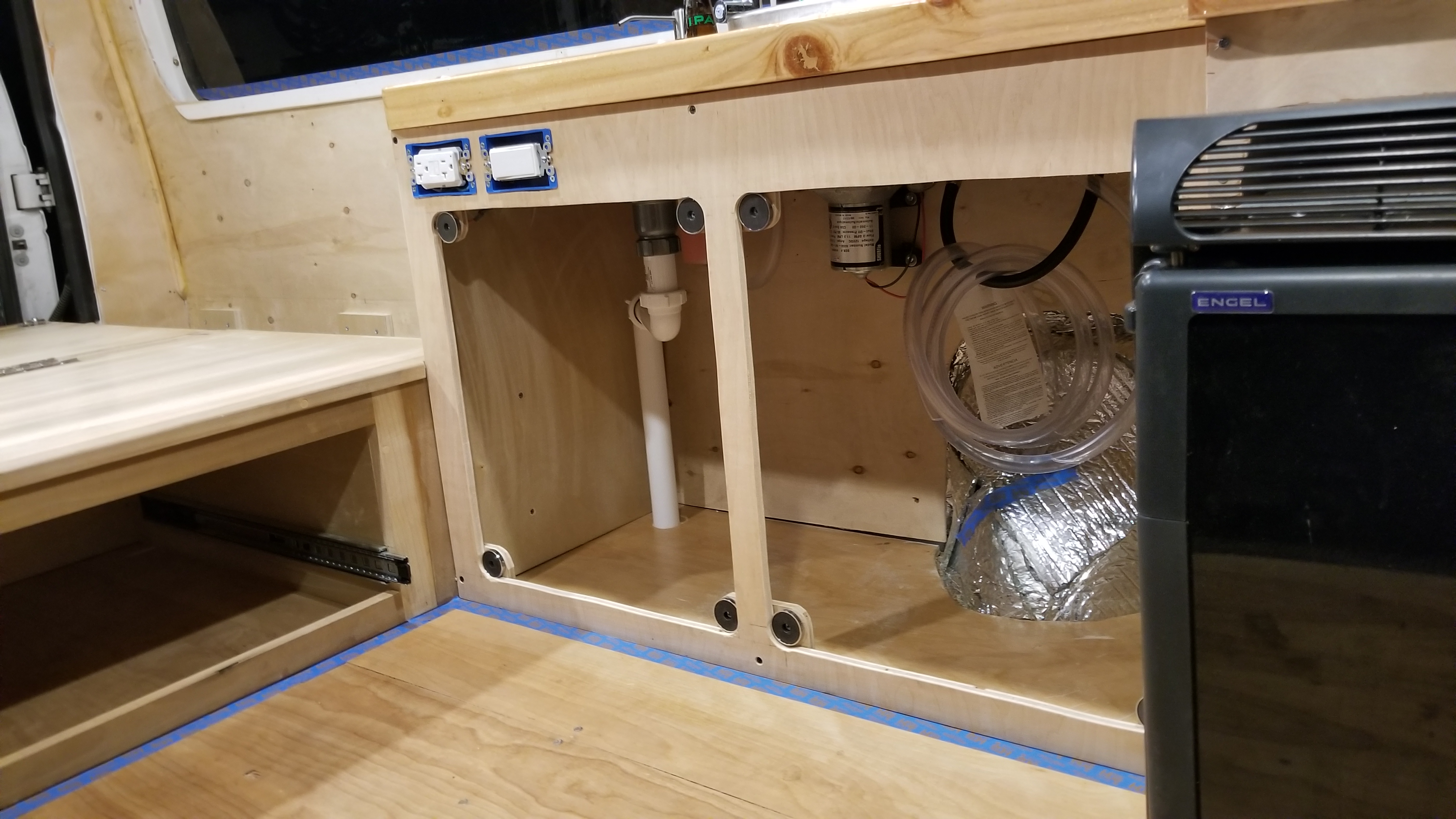
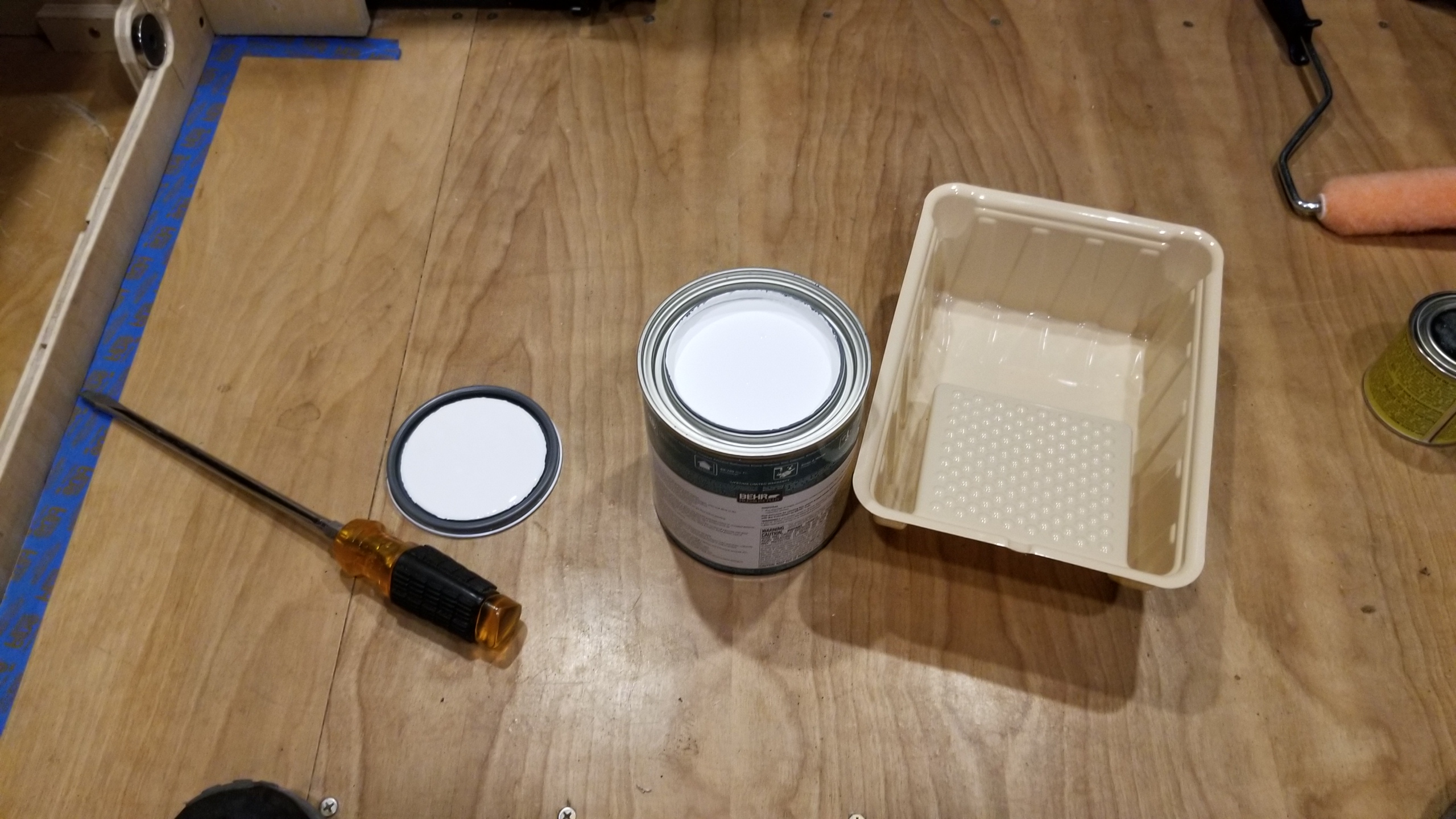
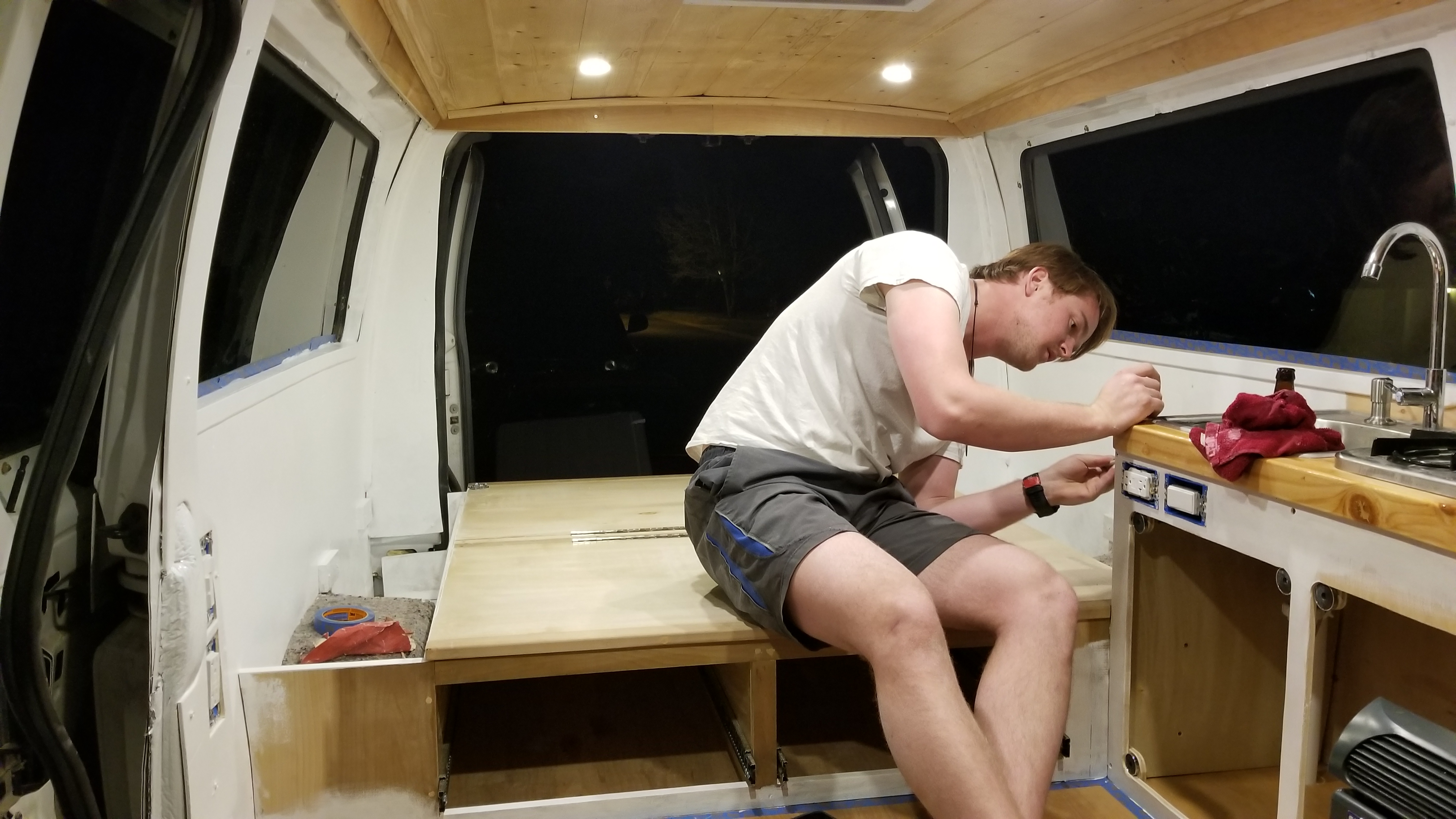
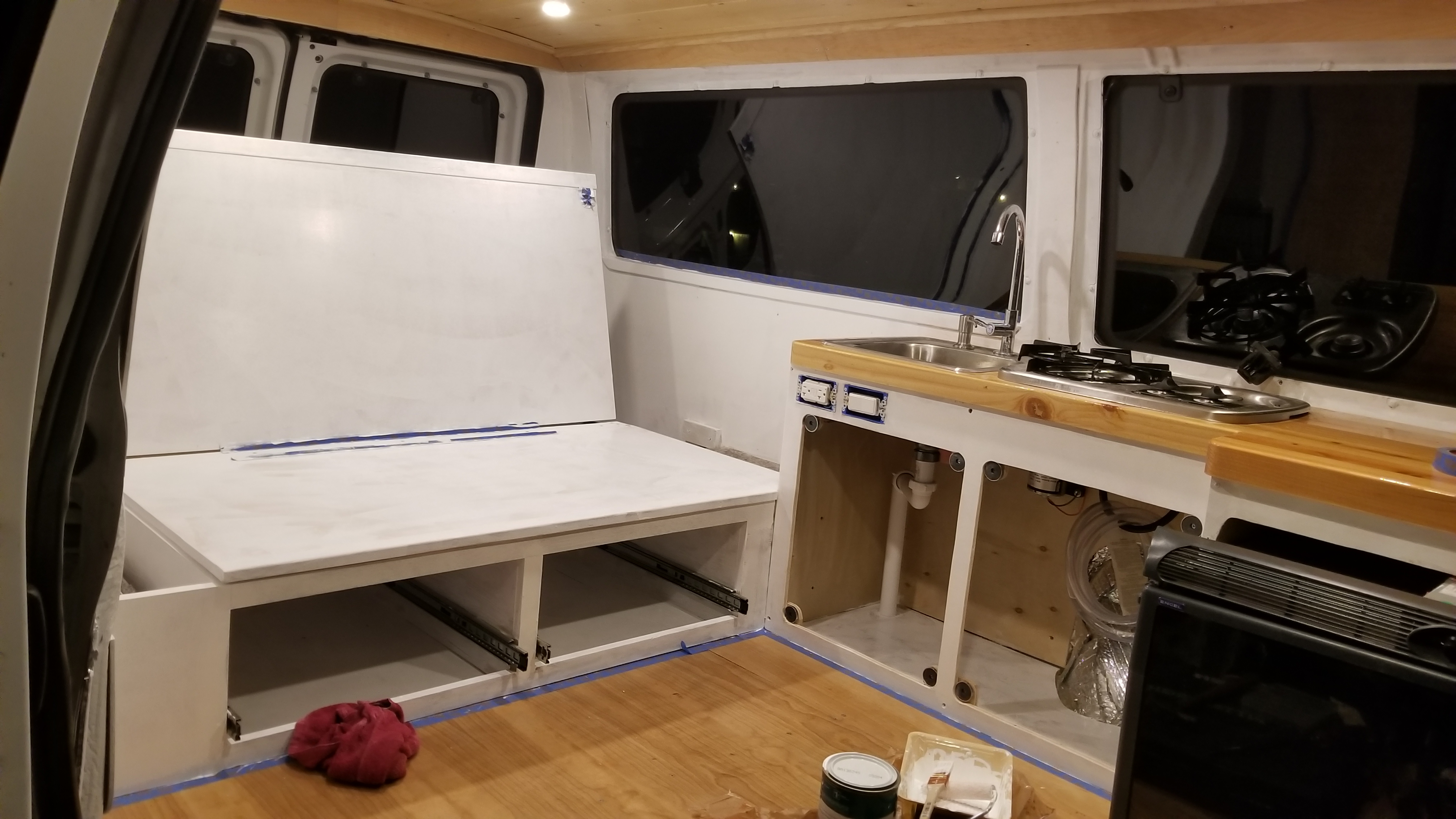
  6. Time to paint! Get your brushes, painters tape, and friends out to help. Tape down any area that you don’t intend on painting. Make sure you use wood putty to hide any blemishes or screw holes. Remove any covers, drawers, or things that you don’t want to have painted from the van. Sand everything down to prep for paint. Vacuum all surfaces and wipe them down. Paint it up (I went with two coats)!
    1. Prep for paint, sand it all!

      Sand, clean, and prep it all!

      Tape it up! Getting it all ready for paint!

      Pop the top and start praying pain everywhere!

    2. Paint the bed frame, inside and out, excluding the drawers.
    3. Paint the cabinet, inside and out, excluding the countertop and cabinet covers.

      My buddie Nick Norwood, working hard. Hell soon be making his own van!
    4. Paint the walls top to bottom.

      Put the elbow work in

      First coat, a little blotchy, but coming

      The second coat will really start to make it all come together!
    5. Paint the stool, inside and out, excluding the top.
  7. Let it dry then replace anything you removed to prep for paint.
  8. Grab the plastic cover for the column just behind the driver’s seat and cut it to fit your new counter. This will be used to cover all the wires that you ran down the column and save your sanity from trying to make a custom cover. Install the modified plastic cover.
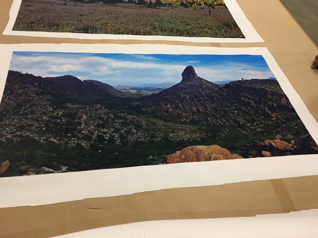
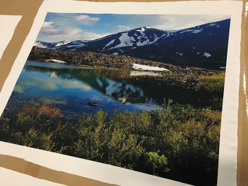
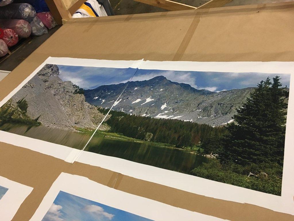
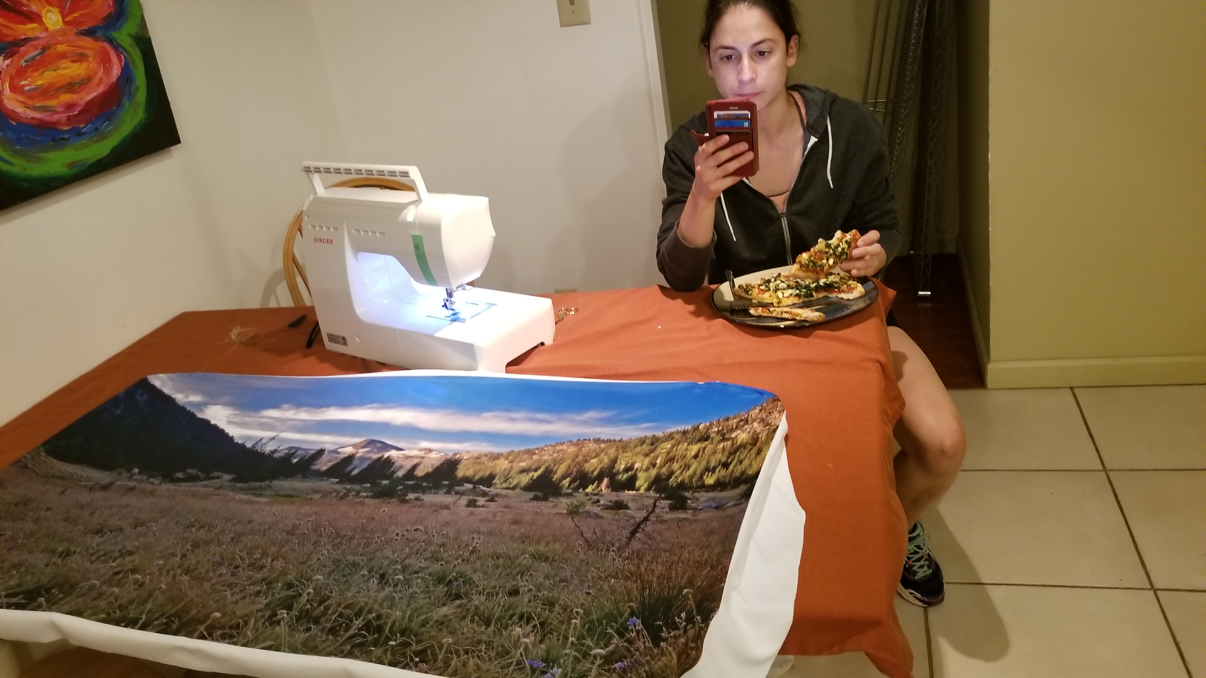
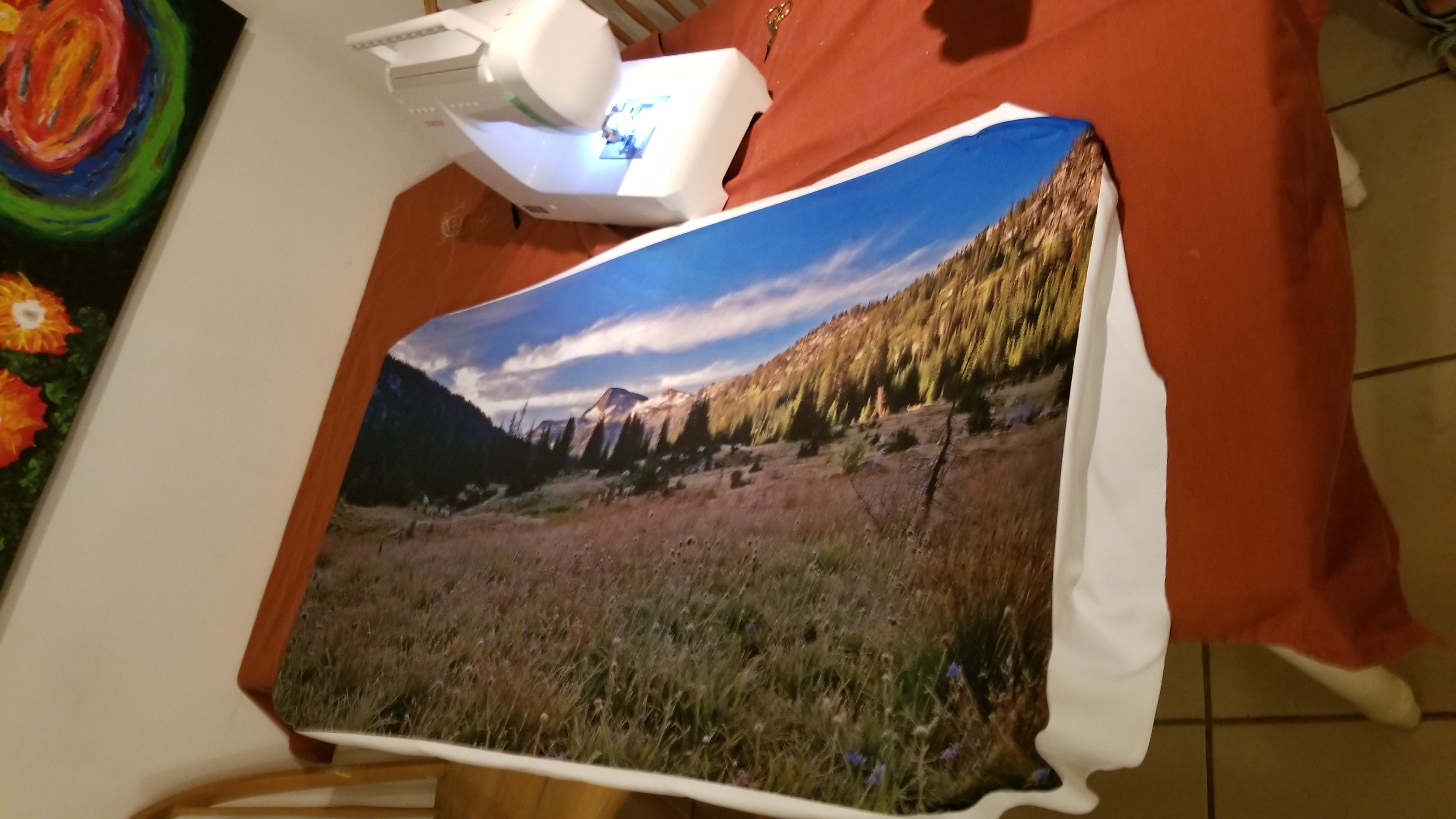
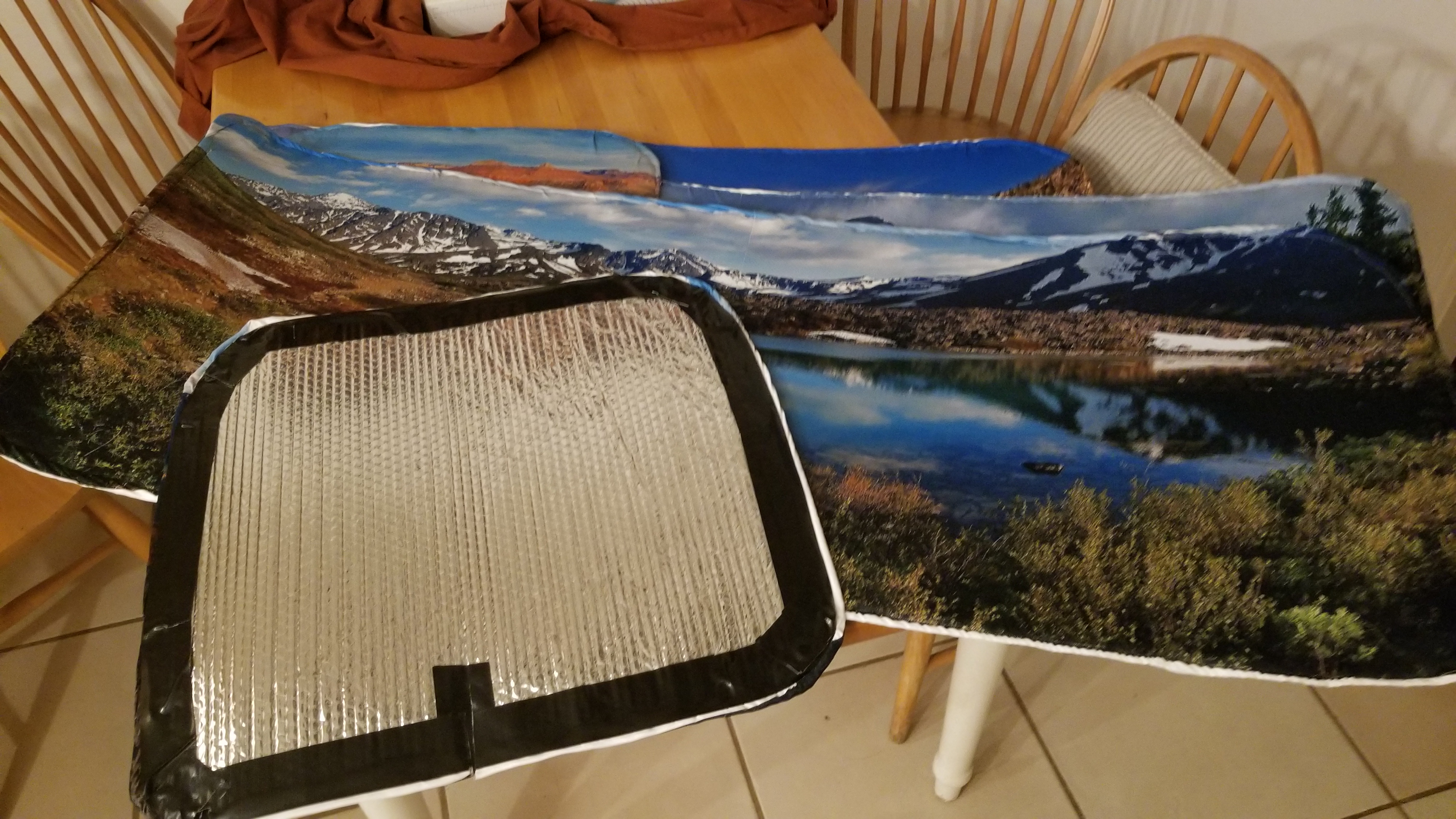
  9. Make the window covers. I used Reflectix to accomplish this, it keeps the heat out and does decently for insulating the windows. I had a friend (Thanks Lyndz!) print out some pictures I loved from treks I had done and I had my old roommate (Thanks Laura!) sew the cloth printed pictures onto the reflexive. I finished it all off with a layer of gorilla tape. I taped on some strong magnets and manually sewed them into place to make sure they didn’t come free.

    RootWares crushing the prints! Sublimating like a boss. https://www.rootwares.com/

    Prints on prints. https://www.rootwares.com/

    piecing them together getting ready for sewing it up!

    Laura Schmidt (FEATZ owner) https://www.etsy.com/shop/Featz

    Crushing the sewing skills.

    Print, sewn onto Reflixic, Gorilla Taped on the edges and Magnets taped to the corners to attach to the inside of the window frame.

    https://www.etsy.com/shop/Featz – Laura Schmidt

    1. Construction Video: https://youtu.be/3gLHX7jIcTs
    2. Installed Video: https://youtu.be/Hq7oZ2Qu_NQ
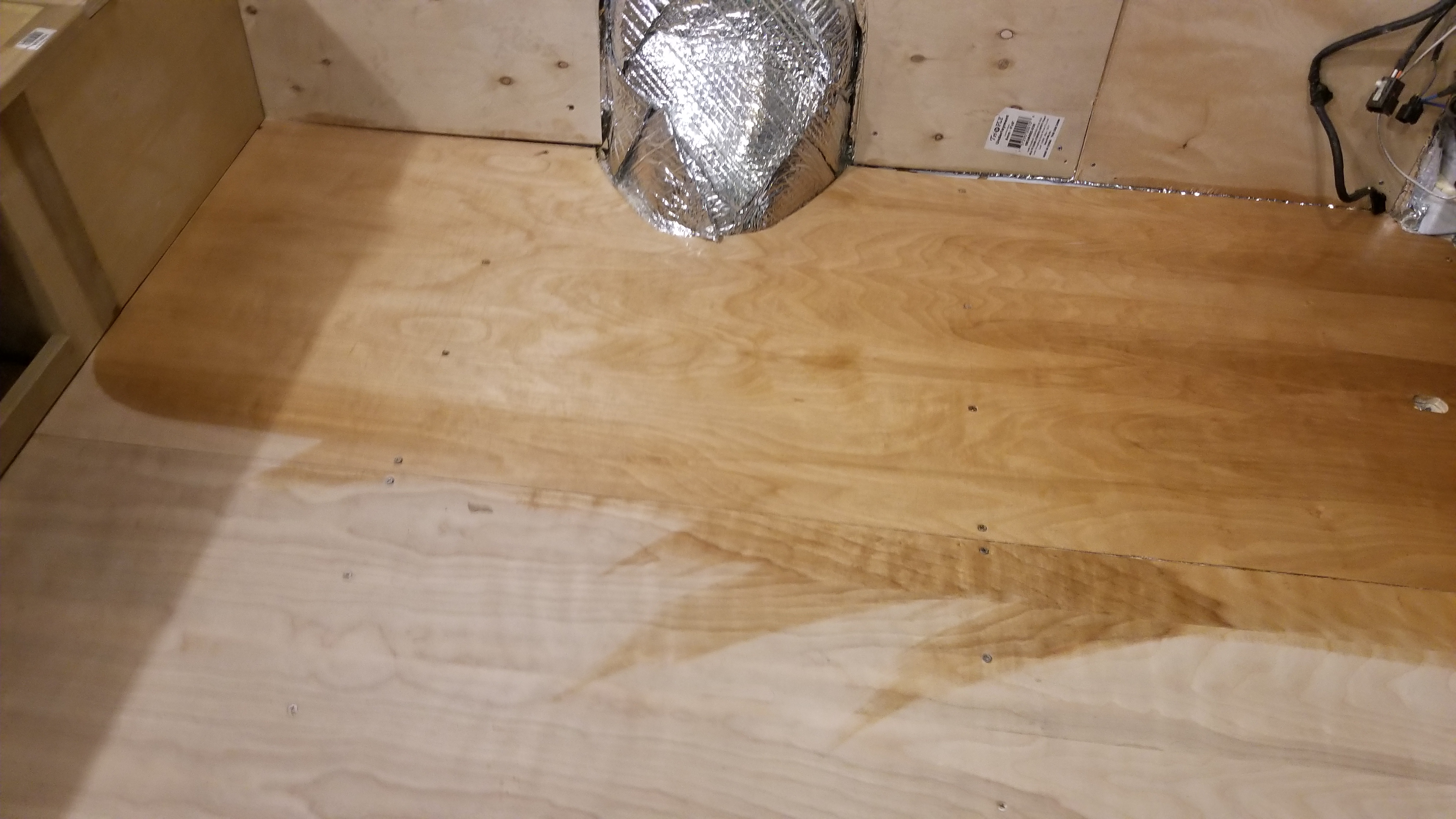
  10. Stain and seal the floor that is still exposed and not painted white.
  11. Replace the plastic step to the sliding door.
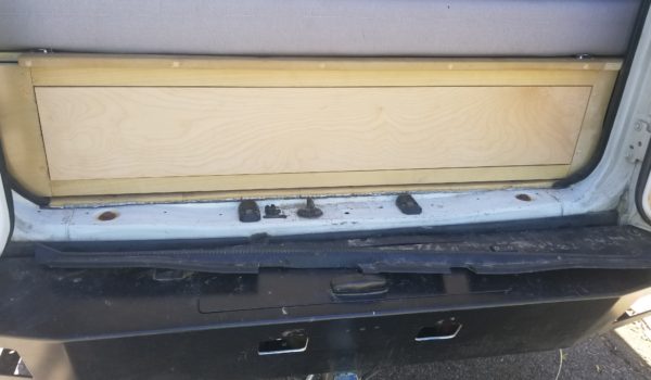
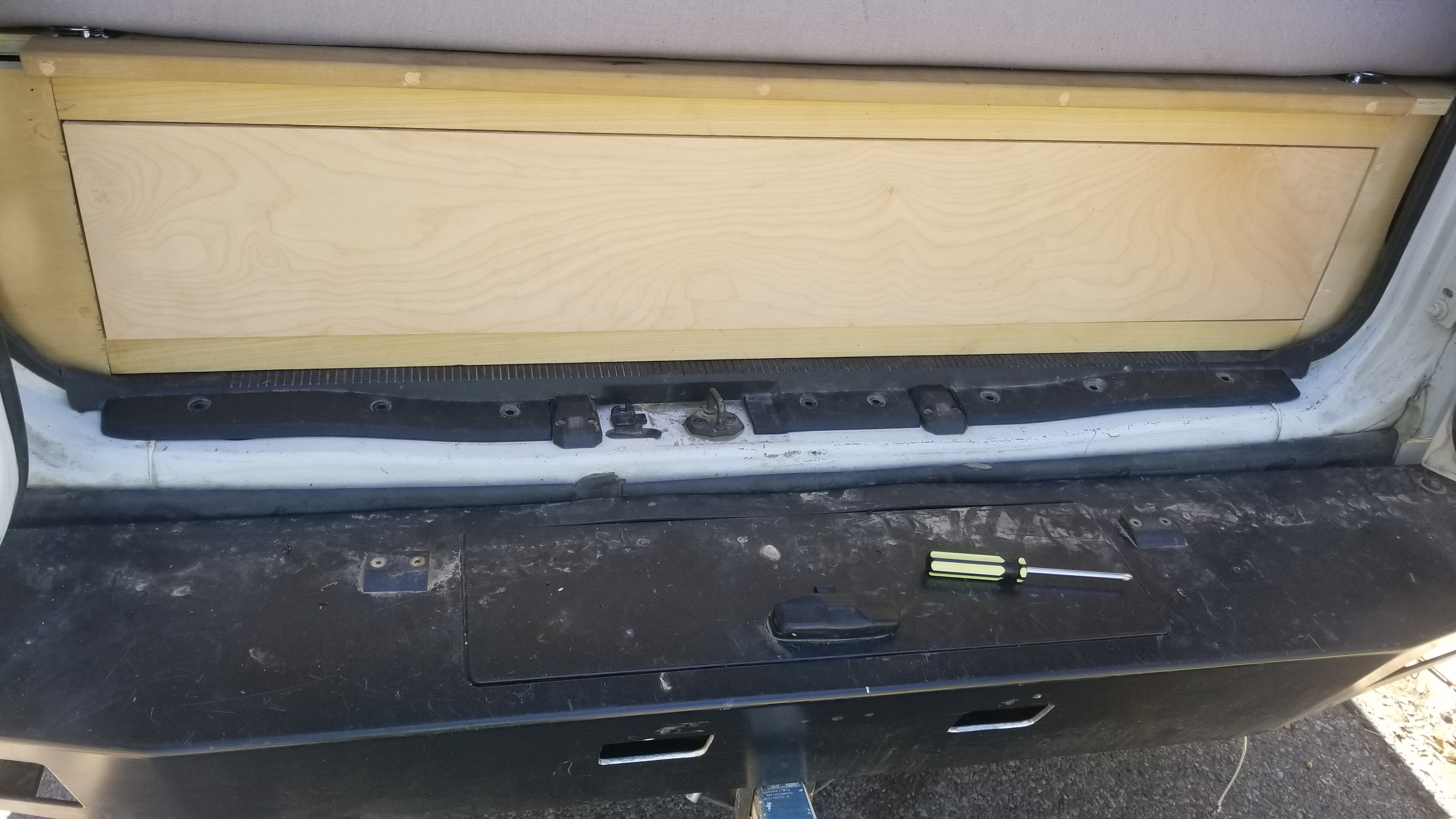
  12. Replace the rear plastic lip at the bottom of the rear doors. I had to modify this to fit below the wooden strip of my rear drawer frame. Once cut in, it really made everything look clean.

  13. Remove your passenger seat base and replace it with a swivel seat. It’s pretty simple overall, just make sure the seatbelt buckle wire does not get pinched. You may need to split the carpet to have it fit over the new base.
    Ford Passenger Base for Factory Seat
  14. Make your sliding door and rear door covers. Once again use thin wood similar to what was used for the walls. Attempt to utilize as much of the existing bolts/screws as possible that held on the original paneling. Stain/seat as necessary.

    Door covers . . . I still haven’t finished mine . . . just being honest!

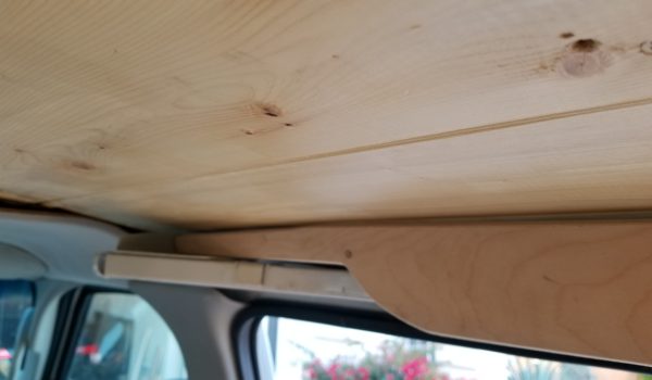
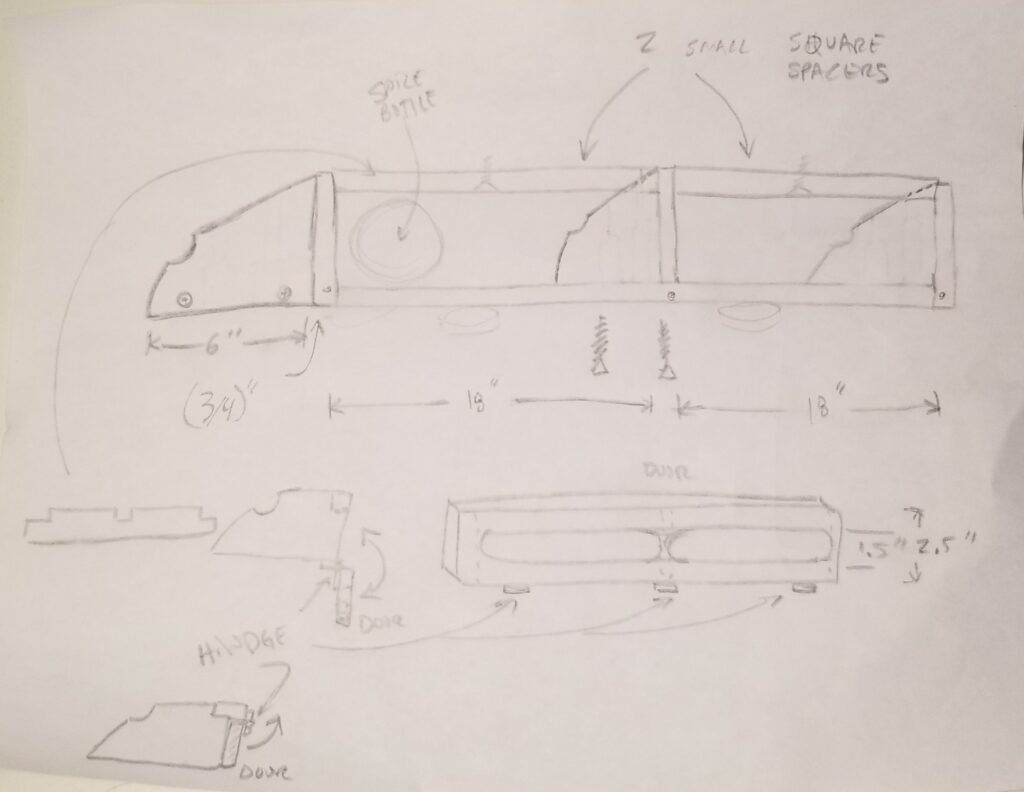
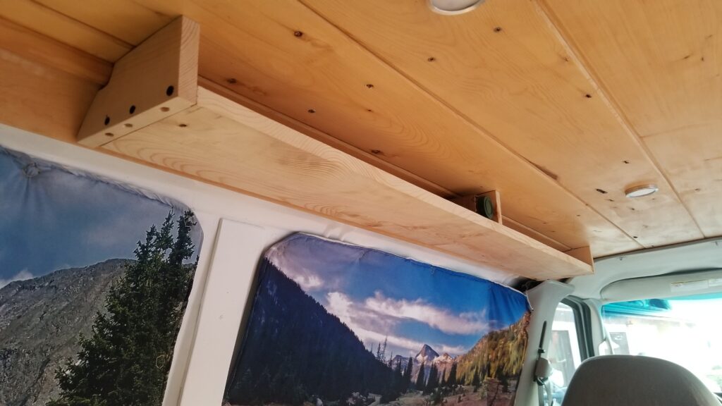
15. Make a spice rack. I used a piece of cardboard to fit the contour between the roof and the facer hang down boards at the corner. From there I sketched up a design and grabbed a 3/4″ x 10″ x 6′ board from home depot.

Sketch up design, even if it isn’t the final design it’s nice to have a plan before wasting time and wood

Cut the spice rack cover (3 1/4″ x 56 3/4″) and the base (6 x 55 1/4″) leaving the rest of the excess wood for the supports you mocked up with the cardboard. Cut the 3 supports out and fabricate to fit flush sanding as needed for fit. Drill bore holes and counter bore holes for the 3 fastening screws that will hold the supports to the ceiling. Screw the end-caps to the spice rack base (with bore and counter-bore holes of course) using 3 screws for each side and hold the structure up and figure out laterally in the van where the rack position should be. Mark the location and drill the end caps into place.

Move the center support into place and mark for final placement

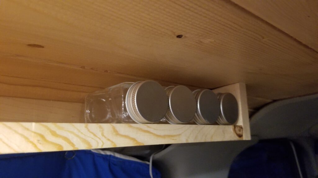
Once in place fit the middle support into place, and figure out how the spice separation should be. I used magnet closures so I offset my middle support a little to compensate. For sanity I threw all the spice bottles I had into place to ensure the spacing was correct before marking the middle support, removing the spice rack base and screwing the middle support into place.

Mock up spice bottles for sanity check

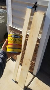
Now that all the wood was cut to size and sanded I stained everything (base, cover, 3 supports still in place screwed to the roof) and put it all back together once it was dry.

Stain time!

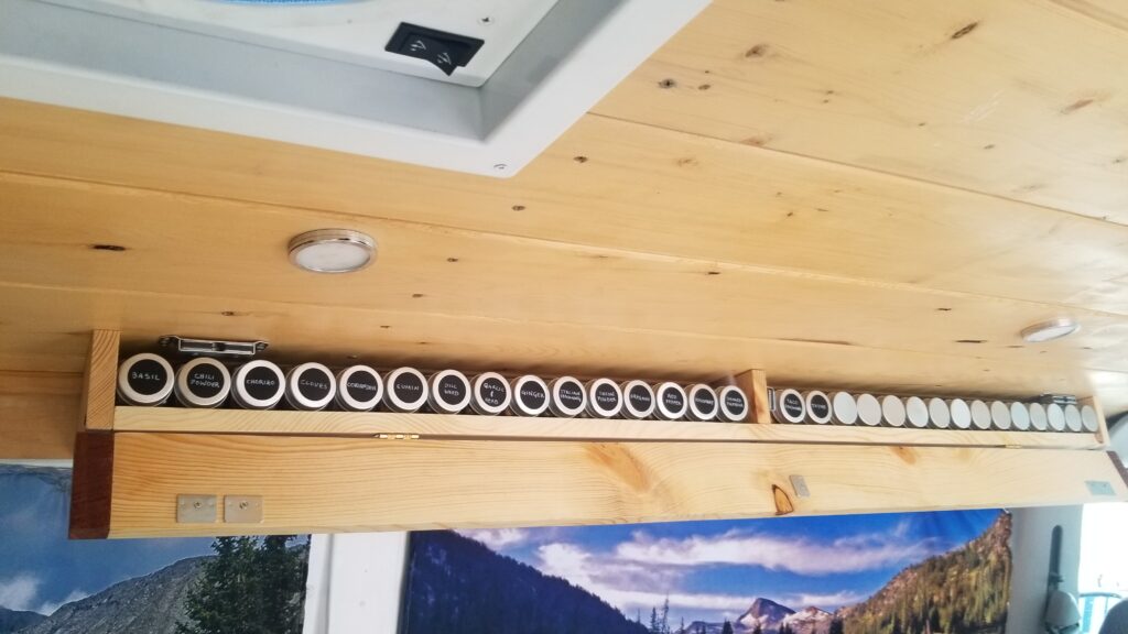
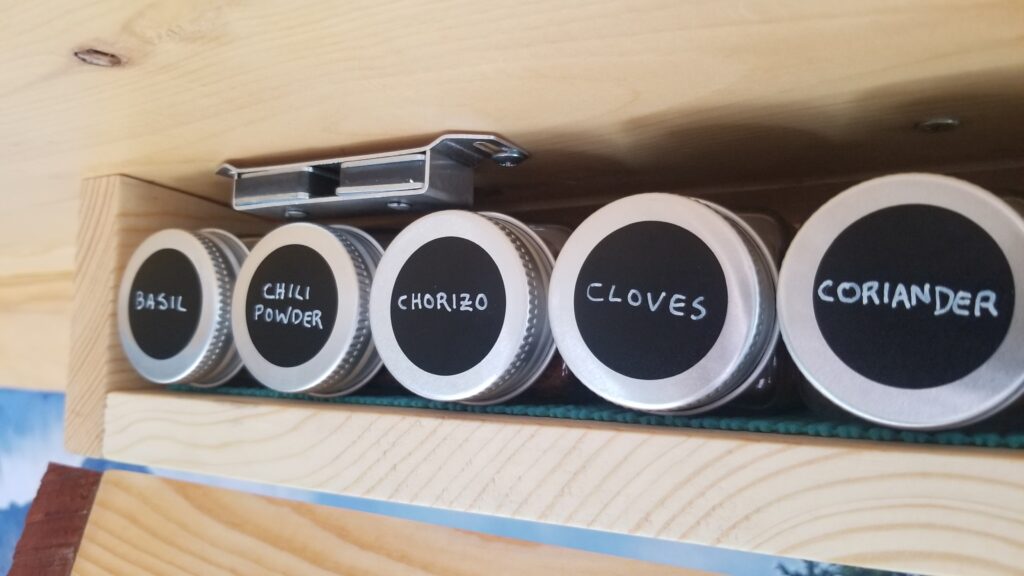
Once dry I grabbed some hinges and screwed the cover into place. To hold the spice cover door closed I used 3 magnet clasps with strike plates for a cabinet doors and screwed them into place (adjust as needed for proper closure). Finally I laid down 2 strips of drawer and shelf liner, cut to size, in the bottom of the rack, held into place with some spray adhesive. Grab all your spice bottles, fill them, mark them, and throw them into your finished spice rack!

Cover open, spices packed, and placed

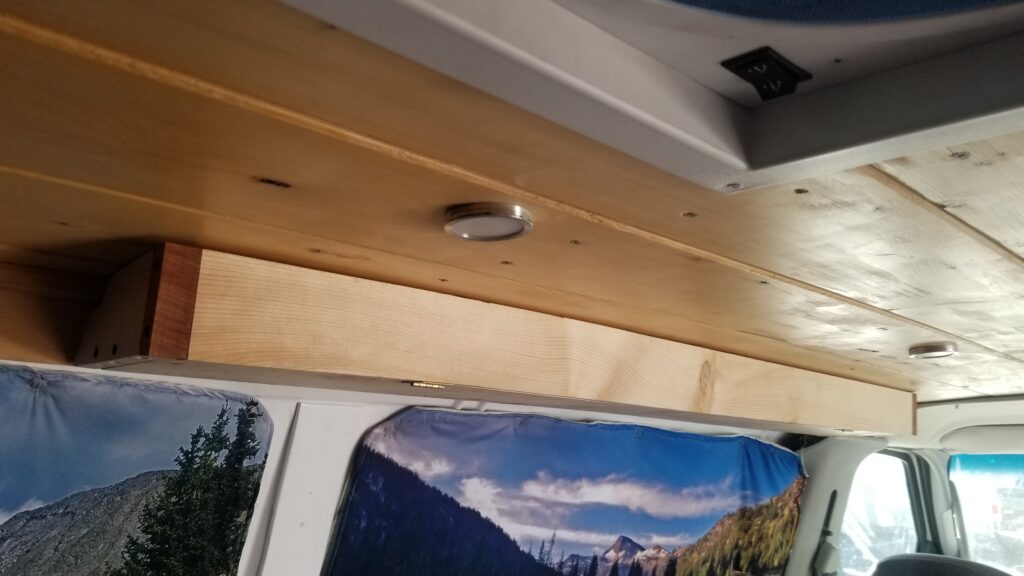
Spice rack, complete, with cover closed

Spices all marked up and in place

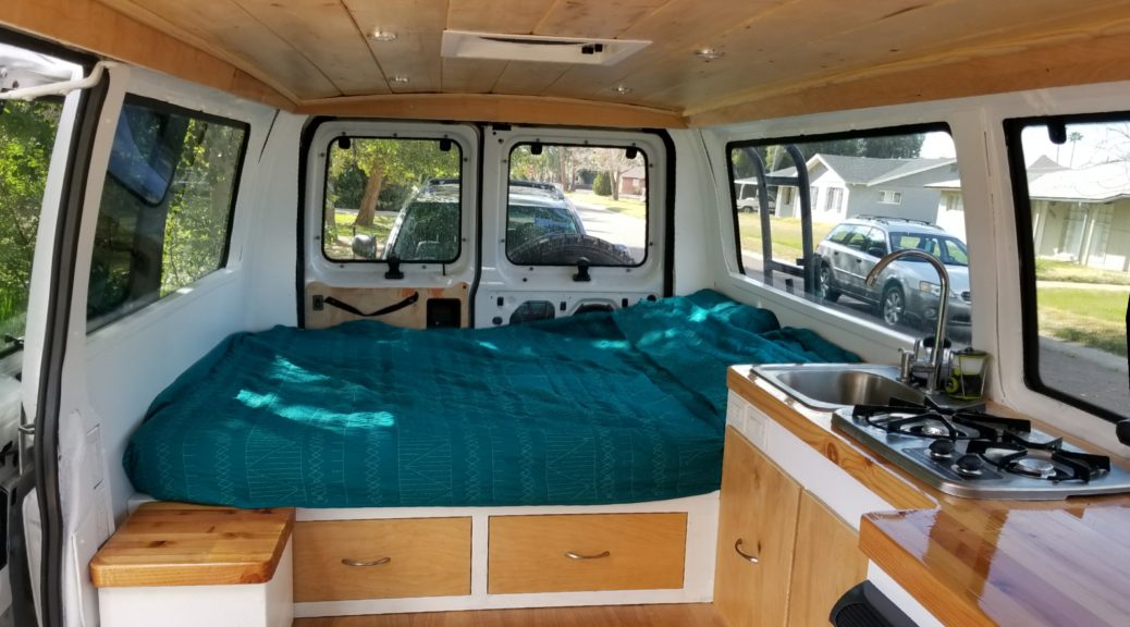
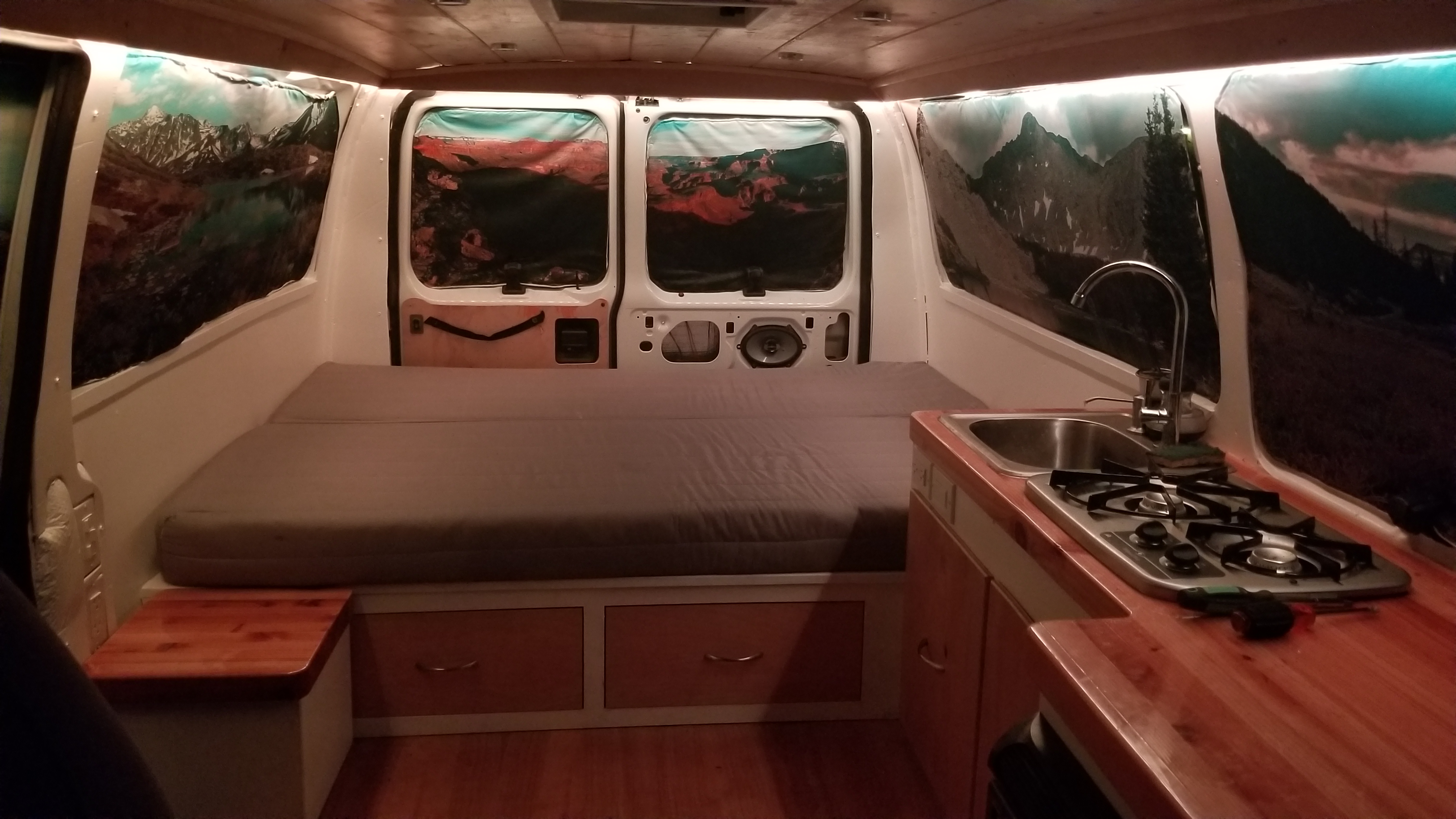
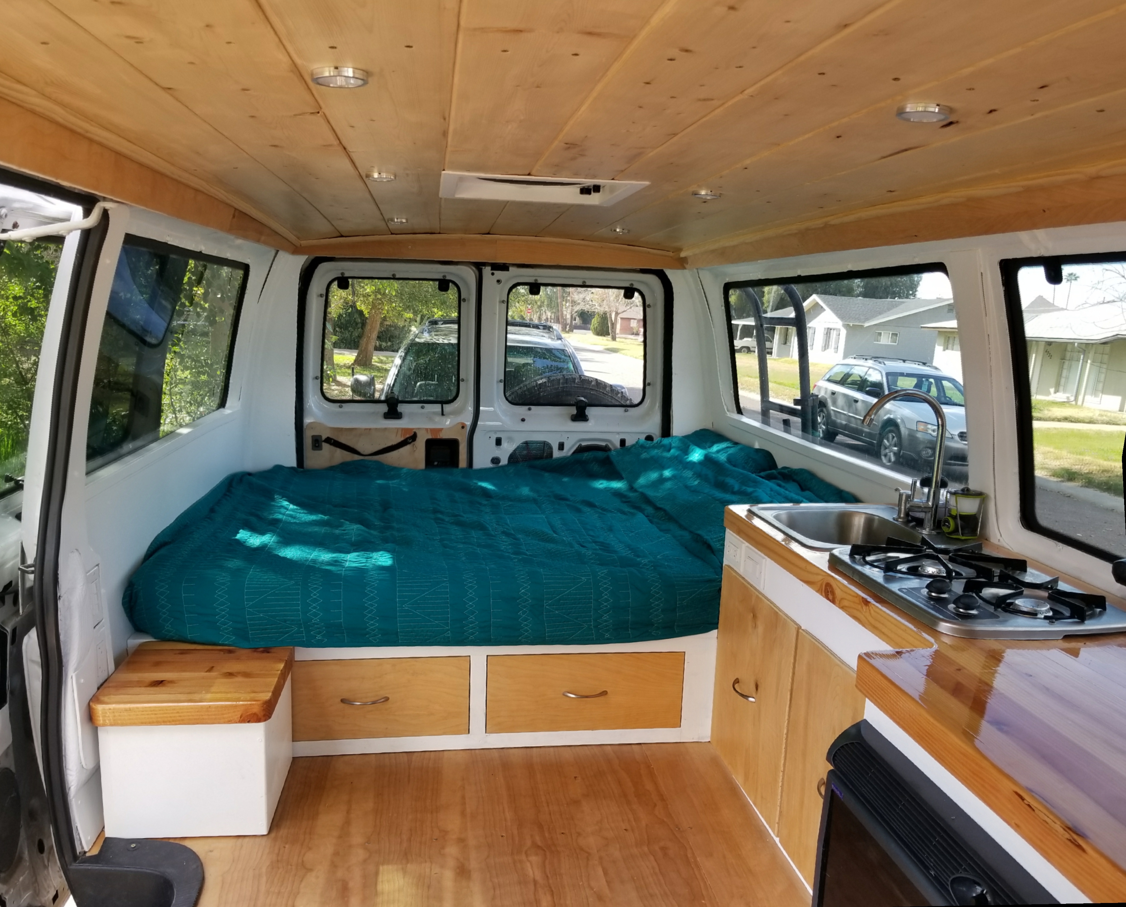
Congrats! You’re long adventure in converting your van is now done, go forth and adventure! Explore all the things and sleep well knowing all your hard work can now truly be appreciated and put to good use!

Share