

Step 4: Start laying out your wire.
It may seem early to be wiring things up, but this critical step will ensure that you don’t insulate over or cover up area where you will need to run wires for your appliances. Decide where your central fuse box will be, you will run all your wires to this location. Your fuse box will be the central place for power distribution. I chose to locate my Fuse Box just behind the driver’s seat. Draw faux appliance locations on the sheet metal with sharpie (lights/ceiling fan) and start running your wires/sheathing. I ran most of my wires right next to the stock wiring harness along the driver’s side corner where the ceiling meets the wall. (A full description of my electrical system will be in the Electrical section).
I ran 18 AWG wire from my components to my fuse box. Check your selected appliances/components manuals which will give you a recommended wire spec. If there is no callout, use an online wire gage calculator to select the correct size of wire (https://www.wirebarn.com/Wire-Calculator-_ep_41.html)
Basic Initial Wiring Outline: More wiring will be added once the cabinet/stove/sink area is installed.
Tools / Materials used:
- Dremel – 4000
- Dewalt Drill 20V Cordless
- Dewalt Drill Bits
- Hammer
- Chisel
- Wire Stripper
- Wire Loom – I used this to run as many wires as possible for organization.
- Qty: 8 x 3/8 in Diam x 10 ft Wire Loom
- Wire Ties – Used for organization
- Qty: 100 x 4 in Cable Ties
- Power Extension Cord – Used for wiring outlets
- Power Outlet
- Qty: 2 – 20 Amp Fused Outlets
- 3 Way Lightswitch – 15 Amp 3 Way Switch
- Shallow Blue Outlet Box
- Qty: 4 Boxes
- Outlet Covers – Wall Plate
- Qty: 2
- 18 gage wire
- 20 gage wire 4 group bundle
- Qty: 1
Phase 1/3: Wiring I ran before insulation:
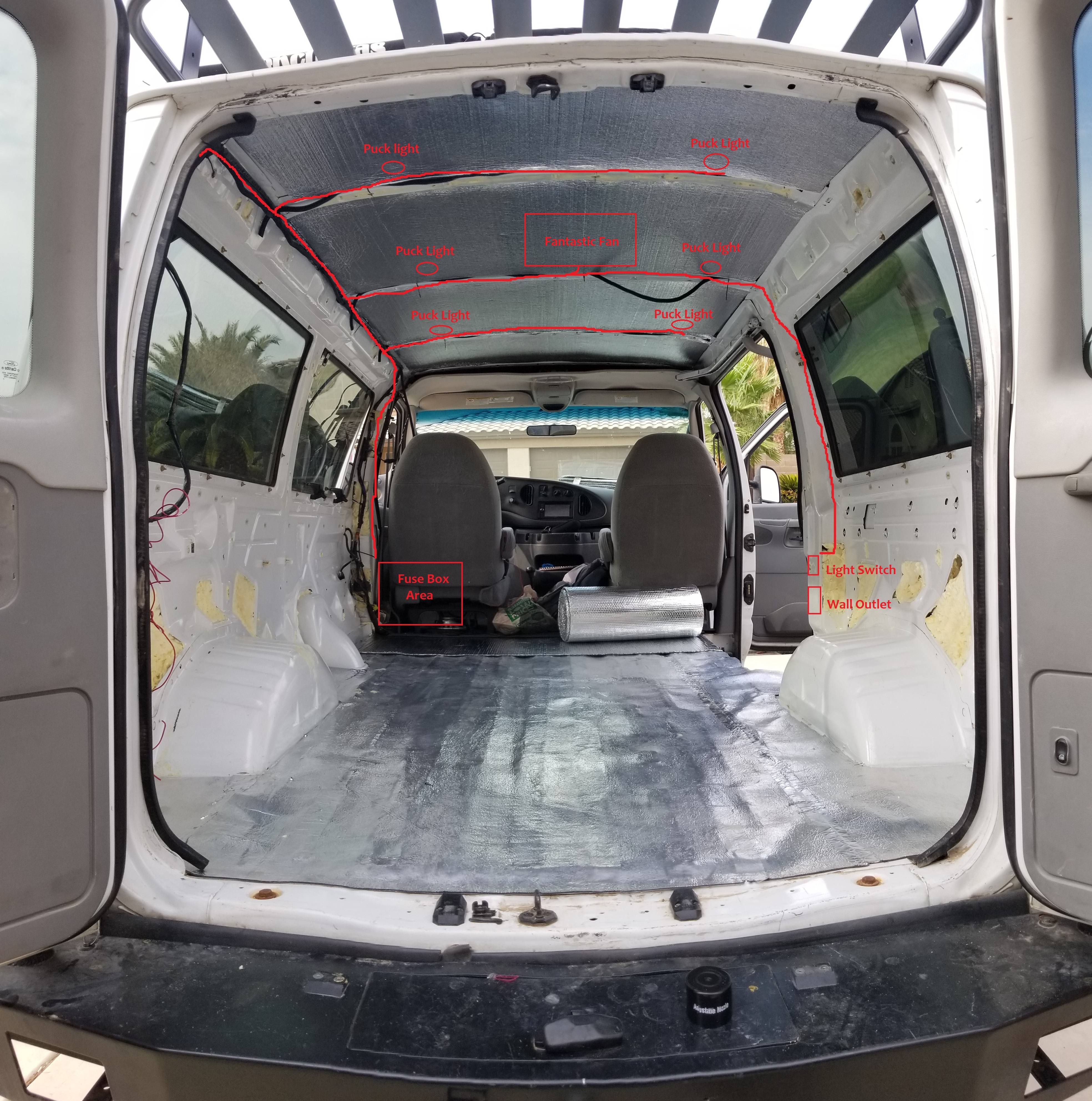
- Wall outlet + extension cord – This will be one of two wall outlets in the van that will be powered by my inverter. Location: Placed on the passenger side of the van, just on the column to the left of the sliding door. I ran the wires up and across the ceiling next to a C brace and along the driver’s side upper ceiling/wall brace down the column to my intended fuse box location.
- Side Note: I cut out the metal from the sliding door column to fit the 2 blue outlet boxes for the 3 way switch and 120V outlet. I drilled 4 holes, 1 at each corner for the box then used a Dremel or Grinder to cut the hole and fit the box in place. I used a chisel and hammer to get some of the metal out of the way. I drilled through the rear passenger window frame (lower left side) from above to run the wires coming down from the ceiling to the boxes now installed in the sliding door column.
-
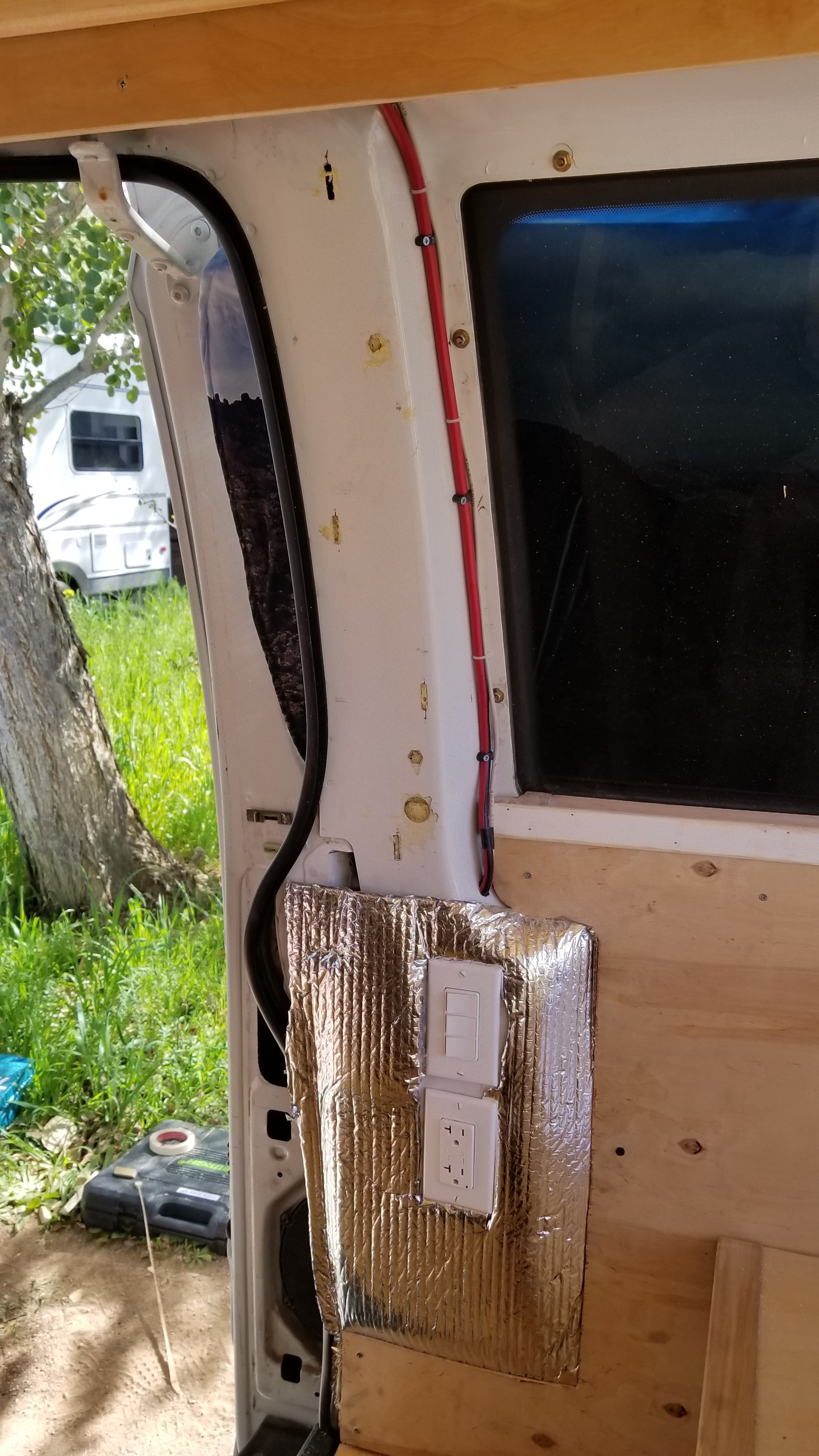
Showing 3 Way Switch and Outlet installed on the sliding door column
- 3 Way Light Wall switches – I will later wire these in to operate my main ceiling LEDs, indirect lighting LEDs, and over the kitchen area LEDs. Location: I put these switches right next to the wall outlet and ran the wires right next to the wall outlets wires.
- Ceiling LEDs – I used 6 puck LEDs on my ceiling and ran wires to their intended locations. I ran the wires next to the stock wiring harness on the ceiling/wall brace then out along each ceiling brace to the puck’s intended location.
- Fantastic Fan – I ran these wires to the general area where I planned on installing my fan (went right next to the puck light wires in the same area).
- Video showing wiring progress: https://youtu.be/XGGkfFPyyGo (don’t be alarmed how far along I am, I just took this video a lot later than I originally planned . . . and with only a headlamp . . . sorry)
Phase 2/3 & Phase 3/3 will be completed later in the build. I added them below for understanding what wiring you will be looking forward to in the future.
Phase 2/3: Wiring I ran during ceiling installation (Covered in more detail in the Electrical Step 10)
- Puck Lights – As I installed my ceiling I installed my puck lights and wired them in. The end of the wires just hung in the fuse box area until I built the cabinet and installed the actual fuse box.
- Fantastic Fan – I opted to install the fan after I installed my ceiling (some want to do this before). Once installed I soldered it into the wires I ran before the insulation.

Phase 3/3: Wiring I ran after cabinet build (Covered in more detail in the Electrical Step 10):
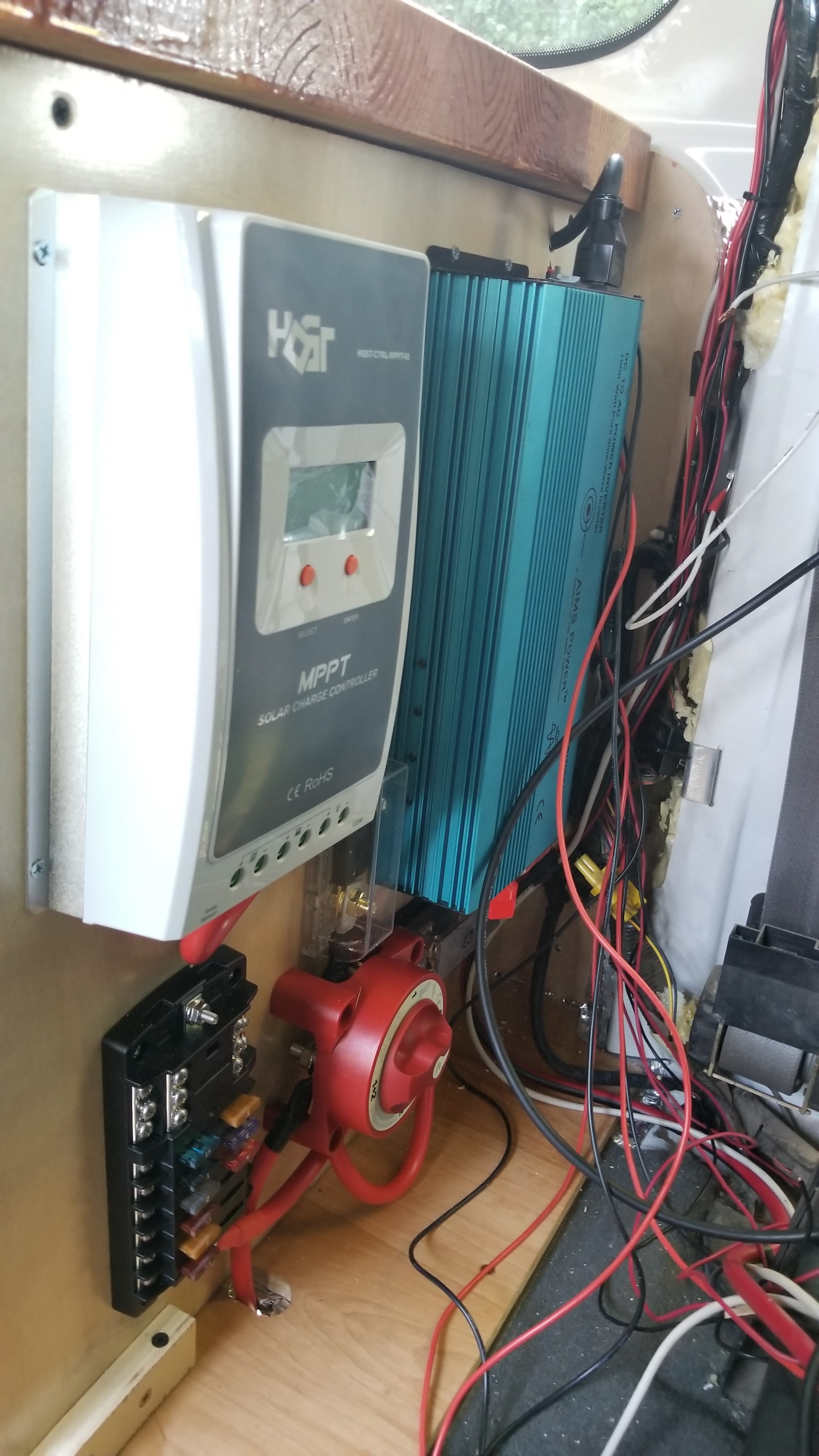
- Charge Controller, Inverter, Fuse Block, Cutoff Switch, Fuses (all per manual specs). Installation will be covered in more detail in the Electrical Step.
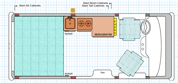
- Wall outlet + extension cord – This will be one of two wall outlets in the van that will be powered by my inverter. Location: Placed on the face of the cabinet. The wiring is ran on the upper back face of the cabinet.
- Wiring for water pump – I mounted the water pump just below the sink and ran the wires along the back upper face of the cabinet to the fuse box. I also included a cutoff switch on the face of the cabinet to turn it off when not in use.
- Refrigerator wiring – I ran the wires through the upper back face of the cabinet through the end to the fusebox once I installed the refrigerator (all per fridge manual specs).
- Video Showing almost complete wiring progress: https://www.youtube.com/watch?v=YqlrzXS5fnU